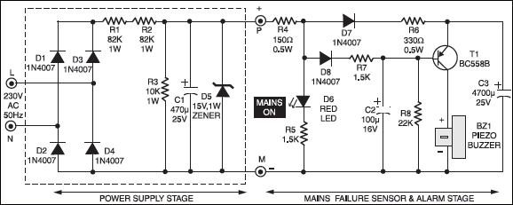
 Most of the power supply failure alarm circuits need a separate power supply for themselves. But the alarm circuit presented here needs no additional supply source. It employs an electrolytic capacitor to store adequate charge, to feed power to the alarm circuit which sounds an alarm for a reasonable duration when the mains supply fails.
Power Supply Failure Alarm Circuit
During the presence of mains power supply, the rectified mains voltage is stepped down to a required low level. A zener is used to limit the filtered voltage to 15-volt level. Mains presence is indicated by an LED. The low-level DC is used for charging capacitor C3 and reverse biasing switching transistor T1. Thus, transistor T1 remains cut-off as long as the mains supply is present. As soon as the mains power fails, the charge stored in the capacitor acts as a power-supply source for transistor T1. Since, in the absence of mains supply, the base of transistor is pulled ‘low’ via resistor R8, it conducts and sounds the buzzer (alarm) to give a warning of the power-failure.

With the value of C3 as shown, a good quality buzzer would sound for about a minute. By increasing or decreasing the value of capacitor C3, this time can be altered to serve one’s need.
Construction & testing
Assembly is quite easy. The values of the components are not critical. If the alarm circuit is powered from any external DC power-supply source, the mains N supply section up to points ‘P’ and ‘M’ can be omitted from the circuit. Following points may be noted:
1. At a higher DC voltage level, transistor T1 (BC558) may pass some collector- to-emitter leakage current, causing a continuous murmuring sound from the buzzer. In that case, replace it with some low-gain transistor.
2. Piezo buzzer must be a continuous tone version, with built-in oscillator. To save space, one may use five small sized 1000μF capacitors (in parallel) in place of bulky high-value capacitor C3.
The article was first published in January 1997 and has recently been updated.


can we used this circuit with SMPS (12v 5amps)
Yes, you can remove the circuit shown by dotted lines on the left, connect your SMPS output to points P and M marked in the circuit.