


 When power-supply polarities of an electronic device are accidentally interchanged, the device runs the risk of damage. The danger can be avoided by adding this tiny circuit to the power supply section of the device. This power supply reversal correcter circuit will instantly correct the interchanged poles of the power supply and warn of the error by raising an alarm accompanied with a visual indication.
Power Supply Reversal Correcter cum Preventer Circuit
The control element is nothing but a relay (RL1). Its supply is made unidirectional by a series-connected diode (D1). Thus in normal state the relay is idle. This arrangement is connected in reverse across the power-supply output. The output of the add-on circuit, which is taken through the normally closed contacts of the relay, via fuse F1, supplies power to the load. This way, unwanted loading of the power supply by the relay is avoided. The normally closed (N/C) contacts of relay RL1 are connected to the input terminals of the power supply in the required polarity, while the normally open (N/O) contacts are connected to the reverse-polarity terminals.
LED1 and LED2 are bicolour LEDs having only two pins each as against the usual three pins. You can also make the 2-lead bicolour LED by soldering the leads of a green LED and a red LED together in reverse polarity.

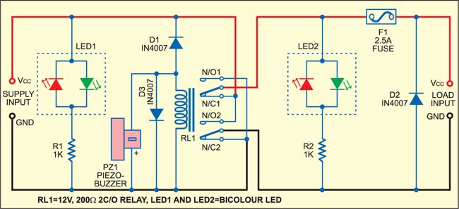
When the input polarity is correct the LEDs glow green, and to indicate error these glow red. LED1 indicates the status of the input DC, while LED2 shows the status of the output. LED2 is primarily used to warn of stuck-up contacts of RL1.
Circuit operation
Another simple protection circuit added at the output of this circuit comprises diode D2 and fuse F1. Diode D2 is connected across the power supply in reverse polarity, so that if the relay takes a little longer to energise during any error, supply reversal forward biases diode D2 and virtually shorts the DC output. Thus the fuse is blown instantly to remove power from the load and the consequent damage to the circuit is averted.

If the supply to the add-on circuit gets reversed, diode D1 forward biases to activate relay RL1. The contacts of relay RL1 change over and so the output is interchanged with respect to the input polarity, resulting in the correct output polarity.
At the same time, piezobuzzer PZ1 also gets forward biased through diode D1 to start sounding the alarm indicating supply reversal. This indication by LED1 and PZ1 goes on until the error is corrected. There is no harm to the electronic device connected to the power supply even if one neglects to correct the interchanged polarities, since they are attended to automatically and corrected.
This circuit is far more efficient than the commonly used diode-bridge protection arrangement because the bridge diodes affect the power supply levels, especially if it is a low-voltage storage battery.
Construction & testing
The circuit can be assembled on the relay itself since all other components like the LEDs and the fuse are mounted on the front panel in their respective holders. The supply input and load terminals can be screw type for ease of connections if it is to be used as a standalone unit.
The article was first published in February 2006 and has recently been updated.
