


Here’s a simple programmable electronic dice with numeric display. This dice can be programmed using a 4-way DIP switch to display any random number between ‘1’ and ‘2,’ ‘1’ and ‘3,’ ….. or ‘1’ and ‘9.’
Programmable electronic dice circuit

IC1 is a dual 4-input Schmitt trigger NAND gate 74LS13. Gate N1 is used as an oscillator built using resistor R2 and capacitor C1 to produce approximately 70kHz clock frequency, which is fed to IC2. Gate N2 loads data at the inputs of IC2.

IC2 is a presettable binary counter (74LS191) with parallel loading facility. Whenever its pin 11 goes low, the data present at its inputs D through A (which is ‘0001’) appears at its outputs QD through QA when all the inner switches of DIP switch are open and DIS1 shows the minimum count as ‘1’ (and not ‘0’).
Circuit operation
To obtain the desired dice range, inner switches A, B, C and D of DIP switch are to be set as per the table. For example, if you want the electronic dice to count from 1 to 8, close switches A and D and keep B and C open. On pressing switch S1, the display varies fast between ‘1’ and ‘8.’ When you release S1, the display stops shuffling and the last (latest) number remains on it.

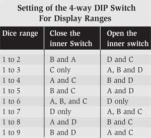
With inner switches of DIP switch in positions shown in the table, the count output can go from ‘0001’ to the maximum count shown under ‘Dice Range’ in the table when switch S1 is depressed. On releasing switch S1, the last count within the dice range gets displayed.
The outputs of IC2 are displayed on common-anode, 7-segment display LTS542 (DIS1). BCD-to-7-segment decoder IC 7447 (IC3) is used to drive the display. Resistor R8 limits the current through DIS1.
The article was first published in September 2004 and has recently been updated.
