 Here we describe a microcontroller-based propeller display that displays any message sent to it via hyper-terminal of a personal computer. Moreover, a temperature sensing IC (TMP125) is mounted onto the propeller display to display temperature in real time. It gives a 360-degree view and displays several characters in a revolving circular path using just eight LEDs. It is a cost-effective, attractive way of display that reduces the cost and complexity while making the whole system dynamic and energy-efficient. The main highlight o this project is a vertical facing display with true 360-degree viewing angle.
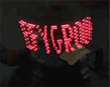
The basic idea of this project comes from the concept of persistence of vision. This phenomenon is related to vision capability of the human eye, where an afterimage is thought to persist for approximately 1/25th of a second. So if someone is observing images at a rate of 25 per second, they appear to form a continuous picture.
In this display, the LED strip moves so fast that one is able to see a matrix of LEDs. The time of a single rotation is divided into several shorter time periods during which each individual LED is kept on/off to display different characters. Temperature sensed by the temperature IC is sent to the controller via SPI bus.
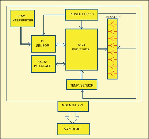
Fig. 2 shows block diagram of the propeller display with a temperature indicator. The LED strip is mounted vertically such that when the motor rotates, the strip also rotates in a circular fashion—creating a true 360-degree display. The message to be displayed is sent via RS232 interface using hyper-terminal. The message is displayed for 30 seconds and then the display switches to the current temperature that is fetched from the temperature sensor. Interrupts are generated by the IR sensor-beam interrupter assembly.
Circuit and working
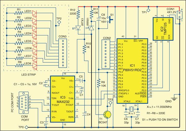
Fig. 3 shows the circuit of the propeller display. The circuit is built around microcontroller P89V51RD2 (IC1), temperature sensor TMP125 (IC2), MAX232 (IC3) and a few discrete components. Port pins P1.0 through P1.7 are connected to CON2, which further needs to be connected to CON3 of the LED strip comprising LED1 through LED8. These LEDs form a circular display when rotated very fast.
Microcontroller. The heart of the system is microcontroller P89V51RD2. The P89V51RD2 is an 8-bit 80C51 microcontroller with 64kB Flash and 1024 bytes of data RAM. It features three 16-bit timers/counters, programmable watchdog timer, eight interrupt sources with four priority levels, serial peripheral interface (SPI) and enhanced UART, programmable counter array with PWM and capture/compare functions, and four 8-bit input/output (I/O) ports. It has an on-chip oscillator and clock circuitry, which is operated up to 40MHz crystal. It supports 12 clocks per machine cycle (default) and 6 clocks per machine cycle mode, which can be selected via software. The Flash program memory supports both parallel programming as well as serial programming.
Power-on reset is provided by the combination of resistor R9 and capacitor C8. Switch S1 is used for manual reset. An 11.0592MHz crystal (XTAL1) along with two 33pF capacitors (C6 and C7) provides basic clock frequency to the microcontroller.
Temperature sensor with digital output. TMP125 is an SPI-compatible temperature sensor available in tiny SOT23-6 package. Requiring no external components, it is capable of measuring temperatures within accuracy of 2°C over a temperature range of −25°C to +85°C and within 2.5°C accuracy over −40°C to +125°C. Low supply current and a supply range from 2.7 V to 5.5 V make TMP125 an excellent candidate for low-power applications. TMP125 is ideal for extended thermal measurement in a variety of communication, computer, consumer, environmental, industrial and instrumentation applications. Port pins P2.0 through P2.2 of IC1 are used to interface the temperature sensor as shown in Fig. 3.
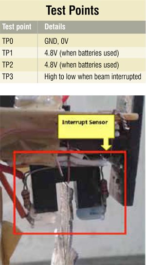
Interrupt sensor. A sensor is built (see Fig. 4) using IR transmitter (IRTX1) and receiver (IRRX1) to generate interrupts. In each revolution, as the beam is interrupted, the sensor generates a positive pulse, which is inverted with the help of a BC547 npn transistor (T1). The inverted pulse is fed to controller port pin P3.2. The microcontroller executes an interrupt routine when a pulse arrives.
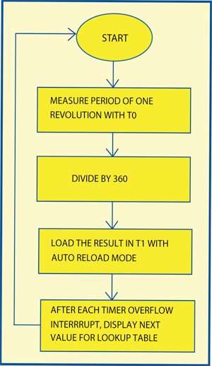
The interrupt routine measures the total time taken for one revolution, divides it by 360 and stores the result in another timer, configured in auto-reload mode. Now the timer overflows after tiny intervals of time. Each time it overflows, the next stored value is called from the lookup table and displayed (refer Fig. 5).
Alternatively, sensor MOC7811 can be used in place of the arrangement that is made using separate IR transmitter and receiver.
Working of the project is simple. Connect the computer to the system using serial port (COM PORT). Open the hyper-terminal and enter the text you want to display (see construction and testing for details). Switch on the motor. You will see the text appear in a short time. The system switches between text and temperature, displaying both for 30 seconds each on the revolving display.
Mechanics
Mechanical arrangement is the most critical part of this project. An AC motor capable of around 1400 revolutions per minute (rpm) is used. The PCB on which the components are soldered is cut into a specific shape in order to improve aerodynamics and reduce any vertical movement. Eight bright LEDs are used, which are mounted on another board that is attached to the main PCB at right angle.
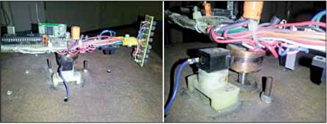
The critical part here is to get the power to the rotating board. There are various ways of doing it. One simple way is to use rechargeable batteries, as shown in the circuit diagram, and mount them over the board such that they don’t come out when the motor rotates. The rugged way of doing this is to use an AC motor with a double shaft. A step-down transformer and a bridge rectifieralong with a 7805 IC can be used to get 5 V from the mains supply voltage. Carbon brush, spring and copper wound bush are used to bring the 5V supply on the main revolving PCB as shown in Fig. 6. The motor should be fitted onto a metal frame in order to reduce vibration of the system and get a smooth operation when the motor revolves.
The number of characters that can be displayed depends on radius, i.e., the distance of the LED strip from the centre. It does not depend on the number of LEDs, which is the main advantage of this system. The main thing to note here is that the speed of rotation directly depends on the radius. A bigger radius would mean a higher angular velocity, which may result in more vibrations. Hence care should be taken not to increase the radius length too much.
Software
The software is written in ‘C’ language and compiled using Keil compiler. Mentioned below are some important functions and their role:
void serial_int (void) interrupt 4 using 0. Interrupt service routine for serial interrupt. It stores indices of the characters entered, by comparing with the ASCII codes array.
void introutine(void) interrupt 0 using 2. Interrupt service routine for external interrupt 0. It is basically a position decoder, which starts timer interrupt while switching between displaying the message and the temperature.
void timer0(void) interrupt 1 using 3. Interrupt service routine for timer 0 (auto-reload mode). It basically displays characters or temperature depending on flag bits, along with blanks in front of the data for scrolling.
Download source code: click here
Construction and working
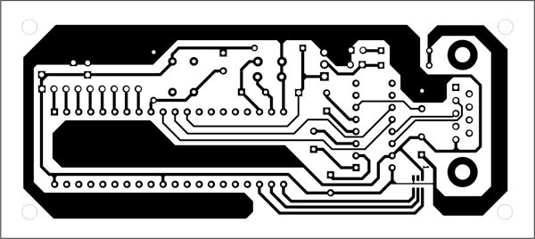
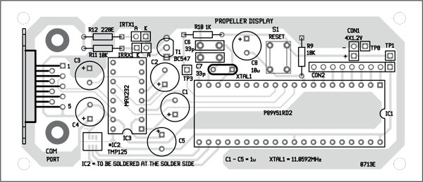
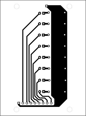
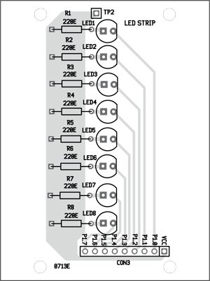
A single-side PCB for the controller board is shown in Fig. 7 and its component layout in Fig. 8. PCB for the LED strip is shown in Fig. 9 and its component layout in Fig. 10. Suitable connectors are provided on both the PCBs to connect them to each other. To avoid loose connection, it is better that you directly solder the wires at CON2 and CON2 to connect both the PCBs.
A proper weight balance of the main PCB is essential before mounting it on the shaft. After approximately finding the centre such that weights on either side of it are the same, a hole can be drilled in the PCB for fitting it on the shaft. Aerodynamic shape of the PCB also helps to reduce vibrations during the rotation.
There are two critical factors in the hardware assembly of this project: One is the voltage supply that has to be transferred at the top of the board. The other is smooth rotation of the PCB that is mounted on the top of a motor shaft. Any miscalculation of the weight would result in an unbalanced system and the required rpm would not be achieved. Moreover, LEDs have to switch in less than 1/25th of a second, which means that in one whole minute it would be close to 1500 times. Hence this is the minimum effective rpm of the motor that has to be obtained after fiting the PCB and the components on the shaft.
To test the circuit, check test points for voltages as per the test point table. For functional testing, follow below-mentioned steps:
- Connect the COM port of the computer to the display system (refer Fig. 3). You can also use a USB-to-serial converter
- Place the interrupt sensor such that the beam is interrupted by the beam interrupter
- Open any hyper-terminal and type the first letter (all upper case
- Wait for change in the pattern of glowing LEDs
- Enter the second letter and wait again for the changing pattern
- Enter the remaining text simi-larly
- When the text is complete, enter space and wait for the changing pattern
- Press ‘Enter.’ All LEDs should glow
- Wait until the LEDs turn off. Now start the motor. The text should appear in some time on the circular display •
Sarthak R. Shah is working at Cliff Electronics, Vadodara, and Abhimanyu K. Varde is working at QLogic, Pune


