


SSR stands for Solid State Relay. SSRs are not very different in operation from traditional electromagnetic relays that have movable contacts. An electromagnetic relay (EMR) generates electromagnetic force when input voltage is applied to the coil.
The electromagnetic force moves the armature that switches the contacts in synchronization. On the other hand, SSRs employ optical semiconductors called photocouplers to isolate input and output signals.
Photocouplers change electric signals into optical signals and relay the signals through space, thus fully isolating the input and output sections while relaying the signals at high speed without any mechanical contacts.

In short, SSRs employ semiconductor switching elements, such as thyristors, triacs, diodes, and transistors. Therefore, SSRs have a variety of features that electromagneticl relays do not incorporate. The greatest feature of SSRs is that SSRs do not use switching contacts that will physically wear out!
Solid State Relay Switch Circuit
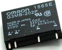
Here is a simple circuit of one microcontroller-compatible dc signal-controlled ac solid state relay switch, designed around an extremely compact G3MB-202P (5VDC) SSR from Omron.

This circuit can be used for switching common electrical loads (lamps, heaters, motors) safely, if the connected load is within its limits. Note that, G3MB-202P is a low-priced subminiaturize PCB mounting single in-line package (SIP) type with inbuilt input resistor, zero-cross, and snubber circuit.
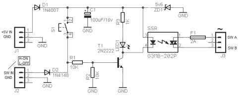
Let’s take a look now at the circuit diagram. The circuit can be powered from a “clean” 5V DC supply. Transistor T1 and associated components R1 & R2 make it possible to accept DC control signal from any microcontroller. The collector of T1 is connected to the input of the SSR to sink current from the positive rail, and its emitter is connected directly to ground rail. Resistor R3 is used to limit the operating current of LED1.
The “slow-blow” (break slowly) 2A fuse F1 is added for total safety and is an essential component here. Similarly, components D1 and ZD1(optional) protects remaining circuit components.
Construction & Testing
The whole solid state relay switch circuit can easily be assembled on a small piece of perfboard. If you are designing a PCB for this, pay attention to the possibility of heavy currents being carried by the PCB tracks linked to switch-output jack J3. After successful construction, start a basic try out as described below:
• Apply 5V DC supply to power-input jack J1
• Take a DMM (put into diode test mode), and connect its test probes across switch-output jack J3
• Push S1 to get a reading (about 0.8 to 0.9) on DMM
• If the reading is available only when S1 is pushed, probably the circuit is okay
Now you can switch an AC240V load routed via output jack J3 with the help of the control signal input (from a microcontroller) given through the signal-input jack J2. Happy Switching!
Important Notes
• Rated output load of G3MB-202P is 2 A at 100 to 240 VAC
• To use this circuit for phase control, replace the G3MB-202P SSR with another one that does not incorporate a zero-cross function, for example G3MB-202PL
• Read more: http://www.ia.omron.com/data_pdf/guide/18/ssr_tg_e_9_1_1-3(overview).pdf
Parts List
• R1-R2: 10K ¼ w Carbon
• R3: 1K ¼ w Carbon
• C1: 100uF/16v Electrolytic
• F1: 2A/240V Slow-Blow
• T1: 2N2222 (or eqvt)
• D1: 1N4007 (or eqvt)
• D2: 1N4148 (or eqvt)
• LED1: Red 5mm/10mA
• ZD1: 5.6v/500mW (optional)
• SSR: G3MB-202P from Omron – see text
Warning
Circuits at live potential should only be constructed/tested/installed by experienced and suitably qualified personnel.
