Lab power supply is the first thing needed by anyone who is extremely passionate about his electronics based experimental work. There are millions of power supply projects already published & available on various online websites & magazines but what makes my project unique lies in the fact that it is built keeping in mind the need of Young Experimenters who are not only tight on budget but also need a simple & easy to make project. Now-a-days DIY Electronics is all about modules so you would find one in this project too. Let’s now dig deep into the building blocks & working details.
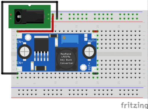
Circuit Diagram made using Fritzing
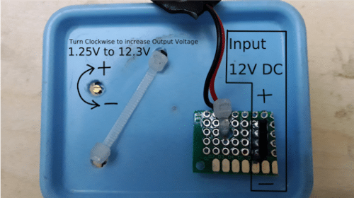
Author’s Prototype
The Module
The heart of the project is this LM2596 based Step down DC to DC Buck converter power supply module which can produce 1.25 Volts to 30 Volts DC output (Available at Robu India Pune for ₹ 79/- exclusive shipping cost).
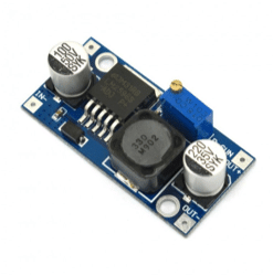

Here I used 12 Volts 2 Amperes SMPS (Switch Mode Power Supply) Power Adapter as Input (Available at Robu India Pune for ₹ 190/- exclusive shipping cost). However you can use any power supply in the range of 4 Volts to 35 Volts DC to power up this module. The module can handle currents upto 3 Amperes. The output voltage can be increased by turning the preset screw clockwise while it can be decreased by turning the screw anti-clockwise. (Image Courtesy: Robu India).
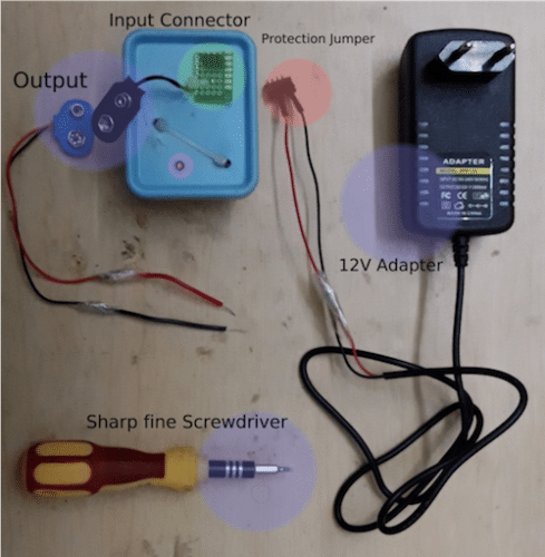
Complete Parts
Construction
The Circuit Diagram of this project is shown here. You can assemble this project on either a breadboard or can place it inside a suitable small plastic cabinet (a soap case would serve the purpose). Make holes in the plastic box using small scissors available in stationary shops. Solder the Male Jumper Wires in place of DC Jack of SMPS Adapter & to prevent shorting insert it in a Female pin header strip as shown in the figure. Solder a 3-pin Female pin header on a small perfboard and connect it to the input of the module. Solder 9V Battery snap connectors to the output of module.
Testing
Hook-up the circuit & connect the output to a multimeter. Turn the Preset Screw clockwise using a Sharp & fine tip screwdriver (as shown in the figure) , the Output voltage should increase. On turning the screw anti-clockwise the output voltage should decrease. The Output is variable from 1.25 Volts to 12.3 Volts & is capable of supplying currents upto 2 amperes.
Tanmay Dasgupta is a freelance Technical Writer & Cartoonist who is currently working as a guest author for EFY online media. His other passions include Robotics & Computer Hardware. He is Diploma in IT Infrastructure Management from CMC Ltd (A TATA Enterprise)