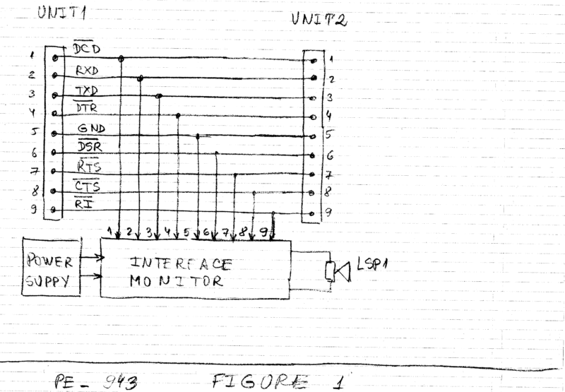
Most of the modern PCs and embedded systems have digital interfaces as RS232, printer ports, LIN, etc. for exchanging of commands and data with intelligent peripherals. Figure 1 is showing typical case of RS232 interface between two computerized units.

Audible monitor circuit
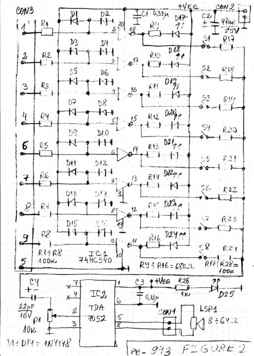
Figure 2 is showing the circuit diagram of simple visual and audible monitor for digital interfaces. Each of the inputs of the monitor has high input impedance. Also each input is protected with diodes. Consequently the inputs of the described monitor can be driven with positive and negative signals exceeding +-30V and the ICs will not be damaged. That is useful for watching digitally controlled peripheral devices and higher voltage interfaces as LIN operating at low speed.
The monitor is built around two integrated circuits (ICs). IC1 is 74HC540. That IC has low input current and high output current which is needed for the LEDs. We can use also 74HC541 or other appropriate buffer in the place of 74HC540. Nevertheless care should be taken because 74HC540 has eight inverting buffers and 74HC541 has eight non inverting buffers (followers).
The switches S1 to S8 are selecting which of the input signals will be monitored audibly. The resistors R17 to R24 are making an AC mixer for the selected signals. The signals are summed over the potentiometer P1.

Usually P1 is selected between 0.51kOhm and 10kOhm and R17 to R24 are selected much higher that P1. That is needed because IC2 has relatively high voltage gain and the signals from IC1 are very strong. IC2 is TDA7052. That IC is selected because it can work in wide power supply range (from 3 to 18V), has high gain and can produce strong audible output signals at low power supply if needed.
The described monitor will start to work immediately after the proper montage is done. The inputs on the connector CON3 can be connected to most analog and digital interfaces working in audible frequency range and below that range. Sometimes monitoring higher frequency signals is possible because the transitions can produce audible signals but more training and attention is needed. The power supply +Vee is 5V but can be anywhere in the rage of 3 to 6V and depends mainly on the ICs in the monitor.
The monitor has three connectors. CON1 is the connector for the loudspeaker LSP1. The resistance of the loudspeaker/headphones is usually between 8Ohm and 64 Ohm and depends on the power supply. CON2 is the connector for the power supply. CON3 is the connector for the monitored input signals.
Construction and testing
The interface is with 9 wires and with connectors with 9pins. During the testing and debugging of the interface boards, cables, connectors and software working with the interface we are in need of monitor of the signals of the interface. For example during the testing we can switch slowly with test generation software the output signals and we can observe the produced effect with LEDs.
Many of the modern interfaces as RS-232, LIN, low speed I2C, low speed printer ports etc. are operating with speeds below 20kHz and consequently they can produce signals in the audible range of the humans. That is interesting feature because we can hear when the communication between the two computerized units happen and there is no need to observe the communication with oscilloscope all the time.
Feel interested? Check out other electronics projects.


