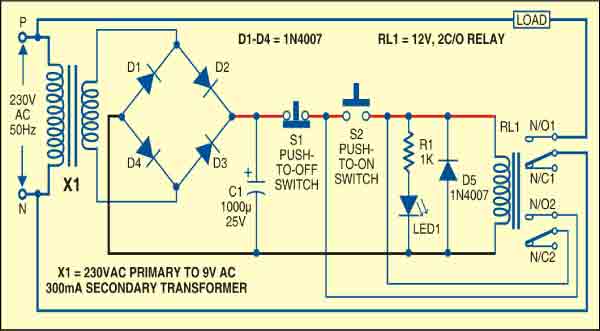
 This circuit lets you switch off and switch on a single-phase appliance using two separate push switches. Such an arrangement is common for industrial motors (mostly 3-phase) where an isolation is required between power and control circuits. Personal protection under faulty conditions is ensured if the relay is placed remotely. The circuit also safeguards costly devices against frequent power cuts as the device turns off in the event of power failure and remains off until it is switched-on again.
The switching-on of the device connected to the relay depends upon the pickup voltage of the relay. When the mains voltage is very low, the output across capacitor C1 becomes less than that required to activate the relay. In this condition, when you press switch S2, the relay does not energise to provide mains power to the device. Thus the circuit offers some sort of under-voltage protection.
The combination of a step-down transformer, a rectifier and a filter capacitor provides the required voltage for activation of relay RL1. Push-to-off switch S1 is used to break the mains power supply from the load (switch off the load). Push-to-on switch S2 is used to connect the mains power supply to the load (switch-on the load). A freewheeling diode across the relay coil prevents the back e.m.f., whereas LED1 gives an indication of relay energisation.
Working of the circuit is simple. When you press switch S2 momentarily, current flows through the relay coil to energise it. As a result, normally-open (N/O) contact of the relay closes to connect the load to the power. The relay de-energises if the power fails or you press switch S1 momentarily to cut the current path of the relay.
Assemble the circuit on a general-purpose PCB and enclose in a suitable cabinet. Mount switches S1 and S2 on the front panel and the relay at the rear side to connect the load.


