


 Presented here is a USB-based real-time data logger system using PIC18F452 microcontroller (MCU), VNC1L-1A USB host controller chip, DS1302 RTC chip and LCD. The system has the flexibility to set time and duration of data measurement.
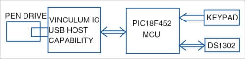
Data loggers are essential for remote data acquisition systems and generally require storage media to store the acquired data. Storage media, like pen drives, require a device with USB host capability or PC to transfer acquired data. A general-purpose MCU does not have USB host capability. Here is a new data acquisition system with a Vinculum chip that provides USB host functionality. Also, by using DS1302 chip and 4×4 keypad, you can set the time and duration of data measurements.
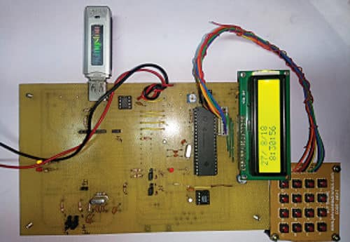
The block diagram of the real-time USB data logger is shown in Fig. 1. The author’s prototype board is shown in Fig. 2.

Circuit and working
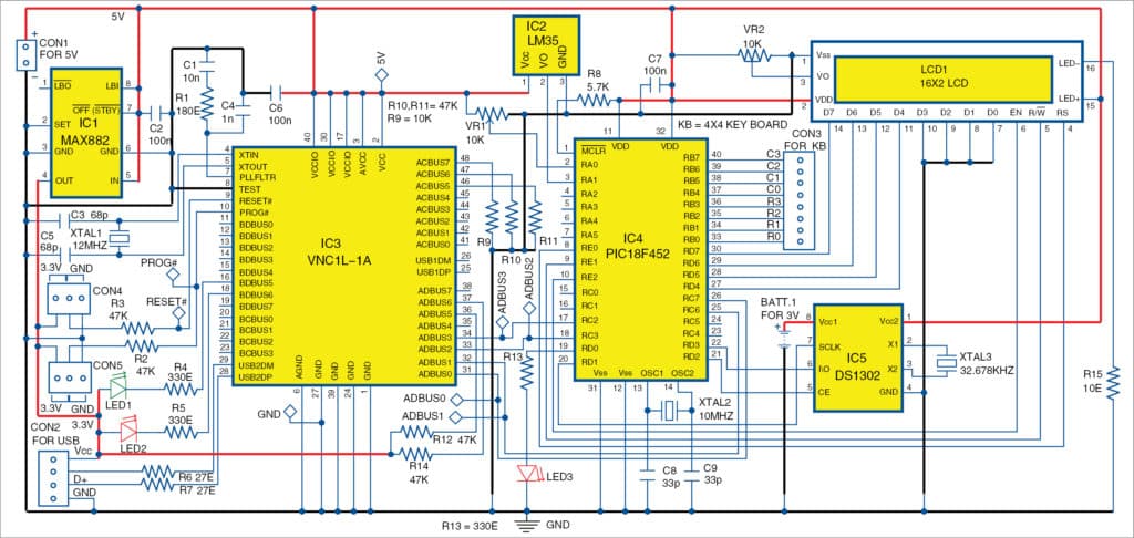
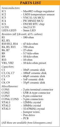
The circuit diagram of the real-time USB data logger is shown in Fig. 3. It is built around 3.3V voltage regulator MAX882 (IC1), temperature sensor LM35 (IC2), Vinculum host controllers VNC1L-1A (IC3) and PIC18F452 (IC4), real-time, trickle charge time-keeping DS1302 chip (IC5), 16×2 liquid crystal display (LCD1) and a few other components.
PIC18F452 MCU provides data acquisition functionality. VNCIL-1A is interfaced to PIC18F452 through UART interface.
VNC1L-1A
It has two USB ports and a combined serial UART, serial peripheral interface (SPI) or FIFO interface. Pins USB1DP and USB1DM carry USB data signals D+ and D- of USB Port-1, respectively. Pins USB2DP and USB2DM carry USB data signals D+ and D- of USB Port-2, respectively.
Port-1 supports USB slave peripherals (not used). Port-2 supports BOMS (bulk only mass storage) class devices such as USB flash drives. Serial UART, SPI or FIFO interface for communication between VNC1L-1A and PIC18F452 can be selected using a pair of pins, ACBUS5 (pin 46) and ACBUS6 (pin 47), by connecting the pins to ground or 3.3V.
UART interface is selected by connecting pins 46 and 47 of IC3 to ground via 47kΩ resistor. ADBUS0 (pin 31) and ADBUS1 (pin 32) carry TxD and RxD signals, and ADBUS2 (pin 33) and ADBUS3 (pin 34) carry RTS# and CTS# signals of UART interface, respectively.
Vinculum provides several pre-compiled standard firmware versions to support different functionalities for VNC1L-1A. For the present application, firmware version VDAP (disk and peripherals) is used. The firmware runs from on-chip 64kB flash memory in VNC1A-1A, and includes a command monitor that allows the external PIC MCU to send and receive command/data via the command monitor interface.
The monitor supports DOS-like disk management commands to perform directory operations (make, delete or list directories), file operations (create, open, read, write, close, delete or rename files) and debug operations (identify or get firmware versions). It also includes commands that allow detection of attachment and removal of flash memory drive to VNC1L-1A.
When the firmware detects a flash drive attached to the USB port, it sends a DOS-like prompt D:\> on the UART interface. It generates codes to flash an LED (LED2) connected to pin 18 when data is written into the flash drive.
The command monitor operates either in command or data mode. In command mode, VNC1L-1A interprets the codes from the monitor port as commands and acts on it. In data mode, it passes data from the monitor port to the USB device. Initially, when VNC1L-1A starts, it stays in command mode. It then signals VNC1L-1A pins ADBUS5 (pin 36) and ADBUS6 (pin 37), which carry DTR# and DSR# signals of serial UART interface, and switches the mode of operation. In the present application, VNC1L-1A is made to operate in command mode by connecting the aforementioned pins to 3.3V through 47kΩ.
Pins ADBUS0 through ADBUS3, PROG#, RESET#, Vcc and GND of VNC1L-1A are used for programming via FTDI programmer.
Remove jumper links at connectors CON4 and CON5 during programming, otherwise pins 9 and 10 should be connected to 3.3V.
More details on Vinculum host controller including FTDI programming are available along with the source code, at source.efymag.com
Software description
A firmware program for sampling two analogue voltages applied on pins 2 and 3 of PIC18F452 at regular intervals of time and storing data in a file in the USB flash drive attached to VNC1L-1A is explained here. The firmware has been written using CCS C compiler and is uploaded into PIC18F452 flash memory.
The firmware includes modules performing the following tasks:
Synchronising UART communication
UART communication between VNC1L-1A and PIC18F452 is ensured by receiving echoes of E and e characters sent from PIC18F452.
Receive Data Available interrupt (INT_RDA) handling
The interrupt is generated in PIC18F452 whenever a byte is received from VNC1L-1A in receive buffer of PIC18F452 via UART interface. The program reads the character and sends to USB flash drive.
Sampling analogue channels
The firmware includes codes to sample analogue channels 0 and 1. Also, CCS C Compiler has inbuilt functions to configure the on-chip ADC for selecting channels and acquiring converted data. These functions can be used by the program for sampling analogue channels.
Codes to write data into USB flash drive
The firmware includes codes to send commands to create Results.dat file in the flash drive, to write twenty values of sampled data into the file and to close the file.
RTC and user interface
In the present design, a user interface is provided with the keyboard for input and LCD for output display to monitor time duration. DS1302 chip provides real-time data to the system. Interfacing DS1302 with an MCU is simplified by using synchronous serial communication. Only three wires are needed to communicate with DS1302 for chip enable (CE), I/O (data line) and serial clock (SCLK) signals.
During read or write operation, CE must be asserted high since this pin has an internal 40kΩ pull-down resistor to ground. SCLK is used to synchronise data movement in the serial interface. Moreover, DS1302 is designed to operate on very low power such that it retains data and clocks information with a power consumption of less than 1µW.
CCS C Compiler provides the driver for real-time clock DS1302 and 4×4 keyboard. Also, the MCU has inbuilt pull-up resistors for Port B pins, which can be enabled using software commands. Hence, connection between the MCU’s Port B pins and the keyboard is given directly. It has the provision to set time range like minute, hour, date and day so that data can be recorded continuously for an entire day, if sufficient power is provided. Time settings can be monitored on LCD1.
Construction and testing
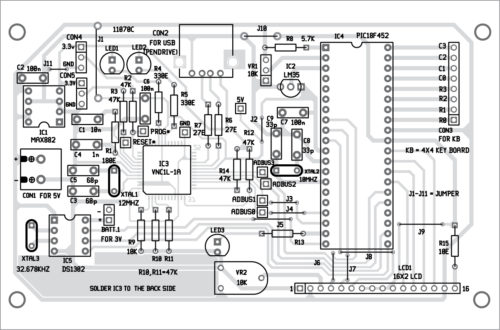
A PCB layout for the hand-held data logger is shown in Fig. 4 and its components layout in Fig. 5. Assemble the circuit on the PCB.
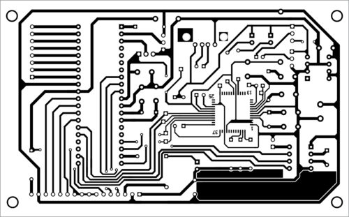
Download PCB and component layout PDFs: click here
Once PCB assembly is complete, burn DataLogger.hex hex code into PIC18F452 using a suitable programmer. After programming, remove it from the programmer and insert it into the PCB. Your circuit is now ready to use.
Insert a pen drive in connector CON2. Connect 5V DC across CON1 to power up the circuit. LED1 and LED2 will flash for two seconds alternatively until a pen drive is connected. Temperature sensor LM35 will automatically sense the surrounding temperature. Glowing of LED3 connected to pin 19 of PIC18F452 shows that temperature data measurement is in progress.
A 10-kilo-ohm potmeter (VR1) connected to pin 2 of PIC18F452 sets a pre-defined reading (say, 2V). That is, two readings are taken and sent to the USB drive—one from LM35 and another through VR1 setting.
Settings and testing
Connect the 4×4 keyboard to CON3 for time settings. An example is given below to feed inputs through the keyboard. Follow the steps given below to test the circuit.
- Check all circuit connections
- Connect the circuit board with a 5V, 500mA DC power supply
- A message reading Starting will be displayed on the LCD. Wait for some time till Press 1 to Start message is displayed on LCD1
- Press 1 on the keyboard
- Press 19 for year
- Press 09 for month
- Press 08 for date
- Press 01 weekday (Sunday)
- Press 08 for hour
- Press 30 for minute
- Press 08 for start hour
- Press 32 start minute
- Press 08 for end hour
- Press 35 for end minute
- Press 00 for hours duration
- Press 01 for minutes duration
In the example above, data logging starts on October 8, 2019 on Sunday at 8 hours 30 minutes. Actual data logging starts at 8 hours 32 minutes. The process stops at 8 hours 35 minutes. Duration of measurement is within one hour (00 in this case) and with updation cycle of every minute.
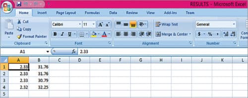
Remove the pen drive from the board. Now you can open the recorded data from the USB using Microsoft Excel or other compatible program. Recorded Data Results file opened using Excel is shown in Fig. 6. The first column shows voltage, while the second shows temperature values. The prototype board was tested with Scandisk 16GB, Sony 32GB and HP 16GB/32GB, to mention a few.
Thus, the USB-based data acquisition system using Vinculum host controller samples the signal at pre-defined intervals of time and stores data in a flash drive.
The, output is saved in Microsoft Excel format, which facilitates quick access to data. Also, Excel format renders further analysis of the data easier.
For downloading Source code: click here
Robson Benjamin is associate professor of Physics at American College, Madurai, Tamil Nadu. His interests include design and development of USB-based data acquisition and automation of electronic gadgets
