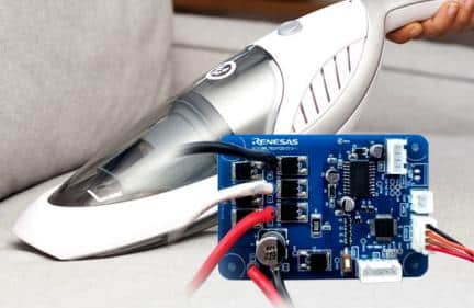
The vacuum cleaner design combines convenience and power, using an air pump, a sensorless 3-phase BLDC motor, and an advanced microcontroller to offer dual suction levels.

A vacuum cleaner, often called a sweeper or hoover, employs an air pump to draw in dust and debris, primarily from floors and other surfaces like upholstery and curtains. Battery-powered hand-held versions are increasingly popular for on-the-spot cleaning, offering a quick, convenient, and efficient cleaning solution. Renesas has launched the reference design for the handy vacuum cleaner to simplify the design process. The reference design for a handy vacuum cleaner allows for the adjustment between two levels of suction power: high and low. The strength of suction for each level is provided by a sensorless 3-phase BLDC motor rotating at high speed. Being battery-operated and cordless, it simplifies vacuuming, making it an effortless one-handed task.
The reference design is based on the RL78/G1F microcontroller unit (MCU), equipped with an integrated programmable gain amplifier (PGA), comparator (CMP0), and a pulse width modulation (PWM) option unit A (PWMOPA) for precise overcurrent detection and PWM output-forced cutoff control. With its 120-degree conducting control, the device’s 4-input selectable comparator and auxiliary motor control timer allow for sensorless rotor position detection, whether the motor is stationary or operating at speeds exceeding 50,000 rpm. Moreover, the ISL94202 Li-ion battery monitor IC manages power, overseeing battery charging and discharging, current and voltage tracking, and maintaining battery balance.
The on-chip features of the handy vacuum cleaner include a debug function, a power-on-reset circuit, a voltage detector, a watchdog timer, a key interrupt function with six input pins, and a clock output/buzzer output controller. It also boasts a Binary-Coded Decimal (BCD) correction circuit, 44 Input/Output (I/O) ports, and an array of timers and serial interfaces. Its converters come in Analog-to-Digital converter (A/D) and Digital-to-Analog converter (D/A) varieties with resolutions of 8/10-bit. Moreover, it has two comparator channels, a Programmable Gain Amplifier (PGA) channel, a data transfer controller, and an event link controller. The standby function can be set to HALT, STOP, or SNOOZE mode depending on requirements. The design operates within a power supply voltage range of 1.6 to 5.5 V and can function from -40°C to +85°C.
The system activates once the Battery Management System (BMS) board’s pack power output plug is linked to the motor control board’s power input plug. To assess battery status, the microcontroller interfaces with the Li-ion battery via the Inter-Integrated Circuit (I2C). The motor’s Negative Temperature Coefficient (NTC) thermistor is attached to its temperature sensor interface. This setup allows the MCU to monitor the motor’s temperature continuously. If temperatures rise beyond 65°C, the motor halts.
Renesas has tested this reference design. It comes with a Bill of Material (BOM), schematics, Printed circuit board (PCB) layout, Gerber files, etc. You can find additional data about the reference design on the company’s website. To read more about this reference design, click here.


