


 The remote-controlled smartfans available in the market are very expensive and their operating principles are difficult to understand. Here is a simple circuit for a remote-controlled smartfan that can control the speed of a fan or light intensity of an electric bulb.
The VIRE remote (Fig. 1) is generally used for MP3 players, FM radios and the like. Its range is up to 12 metres, so there is no need to control the fan/bulb manually. The AT89C2051 microcontroller (MCU) acts as a smartregulator.

Circuit and working
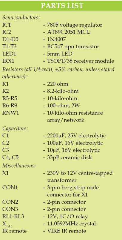
Circuit of the remote-controlled smartfan using AT89C2051 is shown in Fig. 2. It is built around centre-tapped 12V-0-12V, 750mA transformer (X1), rectifier diodes 1N4007 (D1, D2), 2200µF/25V (C1), 100µF/16V(C2) filter capacitors and voltage regulator 7805 (IC1) that produces 5V constant output voltage, AT89C2051 (IC2) MCU, IR receiver TSOP1738 (IRX1), VIRE IR remote, 12V electromagnetic relays, transistors BC547 (T1, T2, T3) and a few other components.

In this project, MCU acts as a smartelectronic regulator based on IR remote signals. It is a 20-pin MCS-51 family controller and has 2kB flash ROM, 128 bytes RAM, UART and on-chip analogue comparator. 12V electromagnetic relays act as switching regulators for positions tapped resistors across R6 through R9 to drop voltage levels to control fan or bulb.
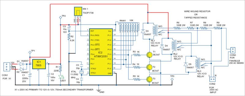
TSOP1738 is a part of IR remote control receiver, which receives IR remote signals and gives IR pulses to AT89C2051 MCU. Output of TSOP1738 is active low, and it gives +5V in off state.

The mains supply is stepped down by transformer X1, rectified by a full-wave rectifier comprising D1 and D2, filtered by C1 and fed to IC1 to maintain constant +5V DC at output. Constant output is fed to AT89C2051 MCU.
Construction and testing
An actual-size, single-side PCB pattern of the circuit using AT89C2051 MCU is shown in Fig. 3 and its component layout in Fig. 4.
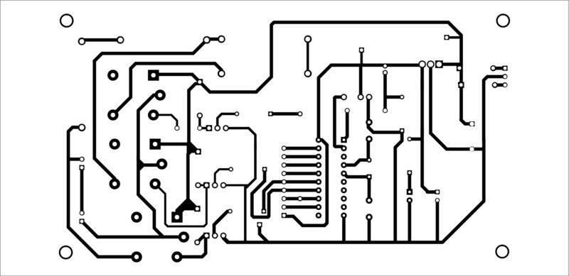
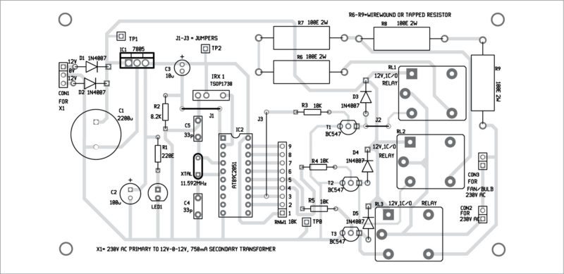
Download PCB and component layout PDFs: click here
Whenever you press a button of the remote, TSOP1738 (IRX1) receives IR signals automatically and feeds it to Port3 pin P3.0 of AT89C2051. The controller receives the sequence of IR pulses and finds out when a button is pressed with the help of Assembly language program in the MCU. In this project we are using only four IR remote buttons, namely, Power, 1, 2 and 3.
Case 1. When you press Power button on the remote, the MCU sends logic low signal to T1, T2 and T3, and automatically making them cut-off (off). Whenever T1, T2 and T3 are in off state, relays RL1, RL2 and RL3 will also be in off state, and therefore the relays’ contacts across the tapped resistors are open. Hence, there will be no voltage across the ceiling fan or bulb. This state is known as fan/bulb off state.
Case 2. When you press 1, immediately the MCU sends logic high signal to T1. This makes T1 to conduct and, in turn, energise relay RL1. As shown in Fig. 1, load (fan/bulb) is connected to 230V AC mains supply through tapped resistors R6 through R9. This should be taken as position 1 or low speed.
Case 3. When you press 2, immediately the MCU sends logic high signal to T2. This makes T2 to conduct and, in turn, energise relay RL2. Load (fan/bulb) is connected to 230V AC mains supply through tapped resistors R8 and R9. This should be considered as position 2 or medium speed.
Case 4. When you press 3, immediately the MCU sends logic high signal to T3. This makes T3 to conduct and, in turn, energise relay RL3. Load (fan/bulb) is connected to 230V AC mains supply without any resistor. This should be position 3 or full speed.
Case 5. When you press a button other than power, 1, 2 or 3, MCU will not take any action. It will simply insert a few delays (in milliseconds).
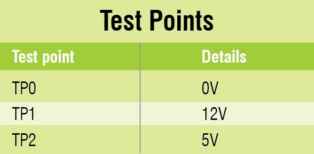
For troubleshooting, check voltages at various points mentioned in the test points table.
Software
The software is written in embedded C language and compiled using Keil Micro vision 4 Version Compiler. It contains simple branch statements to control different fan speeds. We have used TopWin 850 programmer to burn the hex code into the MCU. Follow the following steps to compile the program.
Step 1. After opening Keil uVision, go to Project and create new uVision project. Select New Folder and give a name to the Project as shown in Fig. 6.

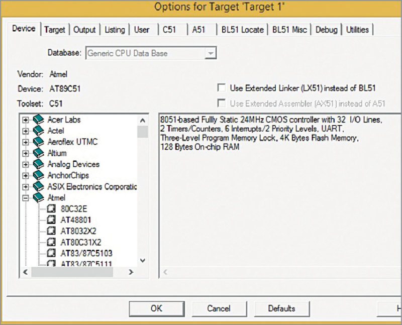
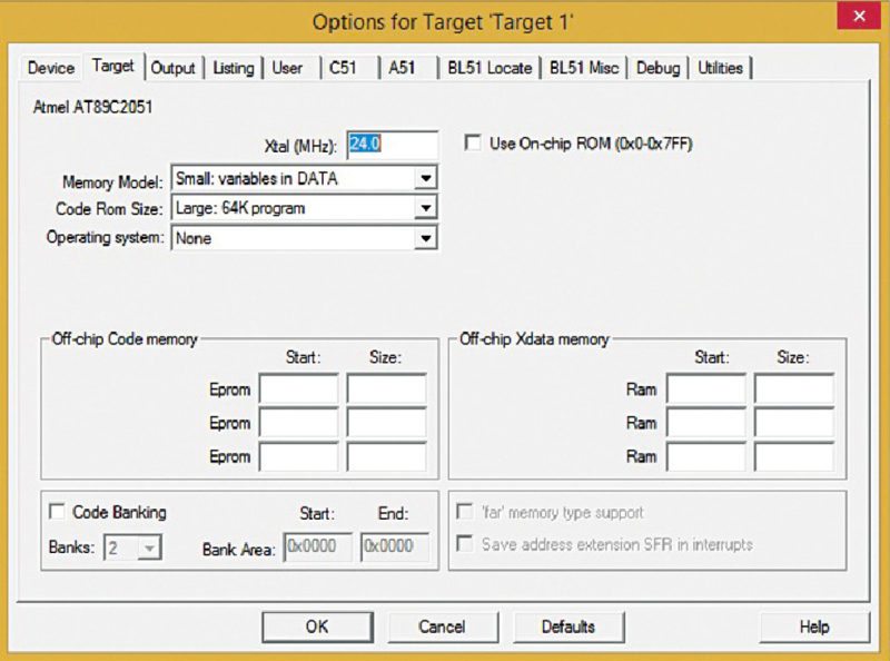
Step 2. After creating a project, select your device model as shown in Fig. 7. For example, AT89C2051. It is available in Atmel package.
Step 3. Now your project is created; a message window will appear to add startup file of your device. Click on Yes to add to your project folder as shown in Fig. 8.

Step 4. Go to File and create a new file. Save it with .c extension if you have written the program in C language, or save with .asm for Assembly language as shown in Fig. 9.

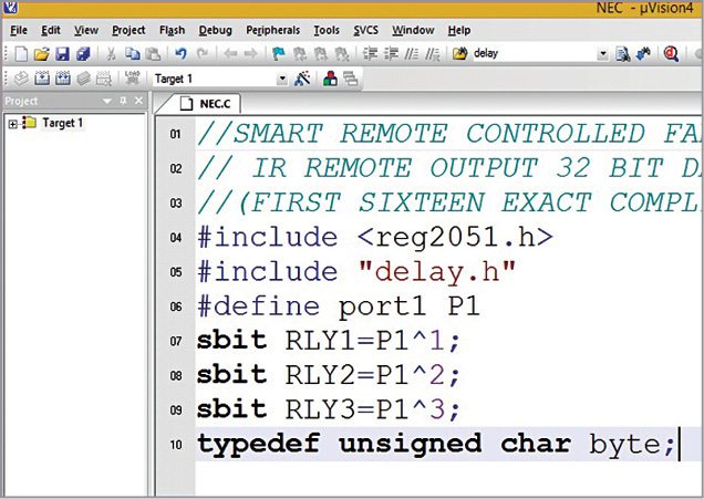
Step 5. Write your program and save it again, as shown in Fig. 10.
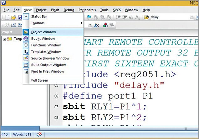
Step 6. On the left you will see the project window. If not, go to View and click on Project Window as shown in Fig. 11.
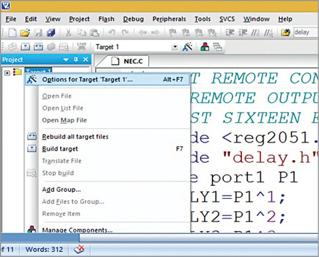
Step 7. After clicking Project Window, right-click on Target and click on Options for Target (Fig.12).
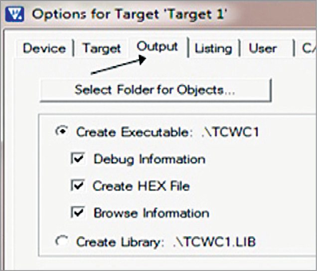
Step 8. Click Output tab and check Create Hex File. Click on OK, so it saves all changes.
Step 9. Expand Target. You will see Source Group. Right-click on Group and click on Add Files to Source Group.

Here, add your program file that you have written in C language. The program file is added under the source group.
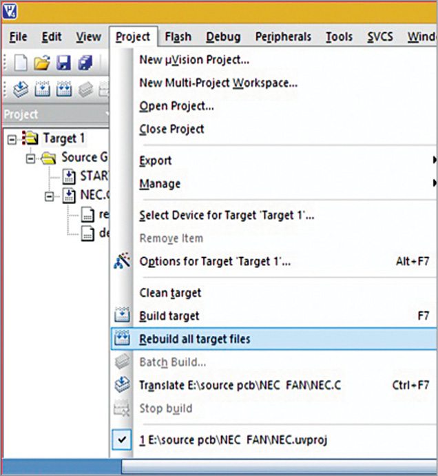
Step 10. Click on Build Target. You will find it under Project or in the toolbar. This can also be done by pressing F7 key.
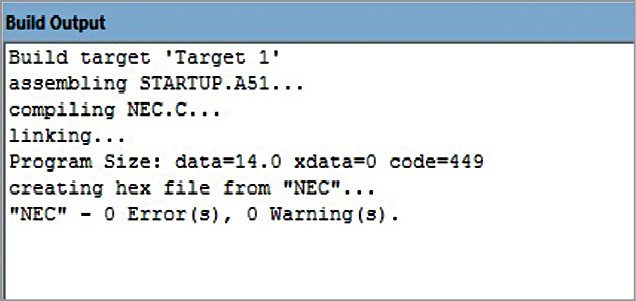
Step 11. You can see the status of your program in Build Output window. If so, you are done with your program.
Download source code
Parmarthi Kanakaraja is assistant professor in Usha Rama College of Engineering and Technology, Andhra Pradesh

From where can I get the compiler…? How do I burn the microcontroller….? Plz send me ans in my mail…