


 In unmanned lifts or elevators, sudden power failure cannot be detected from the remote operating room, and this can prove dangerous for the lift users. Here is a simple remote emergency alarm circuit that sounds an alarm in the remote lift/elevator control room in the event of power failure. The circuit operates off a 6V DC battery.
If the power shutdown continues, the buzzer would keep sounding and drain the battery. To prevent the battery from draining, the buzzer is made to stop sounding after a predetermined period. As soon as power resumes, the alarm circuit disconnects from the battery and the battery starts charging from mains.
Remote Emergency Alarm Circuit
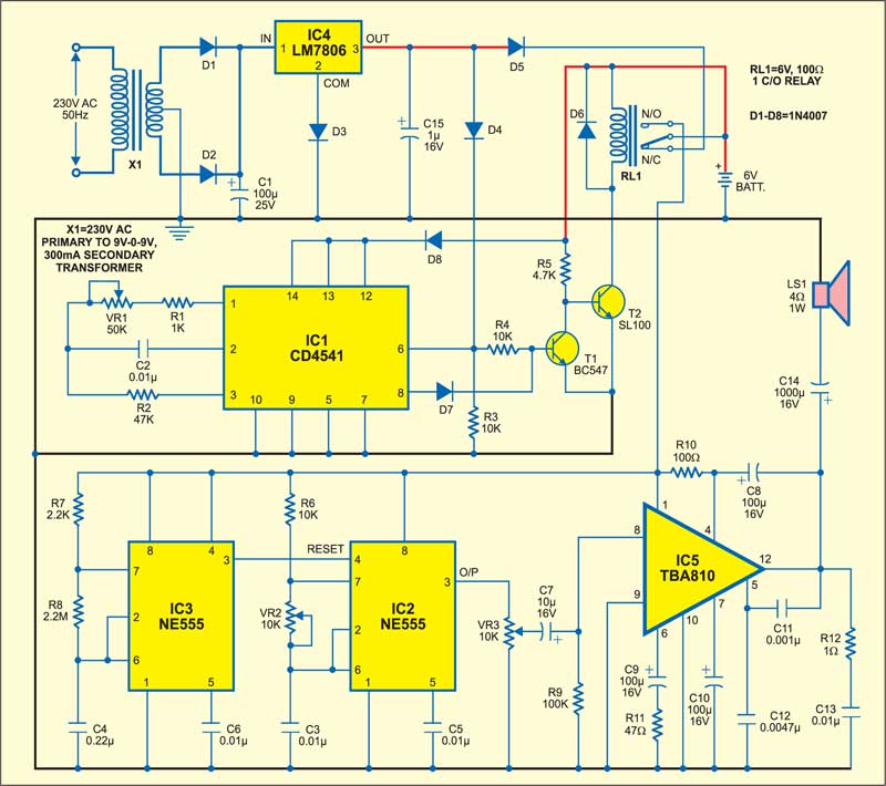
For charging the battery, 230V AC mains is stepped down and rectified by diodes D1 and D2. The battery is charged through diode D5 and the normally-closed (N/C) contacts of relay RL1.

During this time, transistor T1 conducts because diode D4 is conducting, and that drives transistor T2 into cut-off region. So relay RL1 de-energises and the battery continues charging up.
Circuit operation
When power fails, transistor T1 cuts off to drive transistor T2 into conduction and relay RL1 energises. Now the battery disconnects from the charging position and connects to the normally-open (N/O) contacts of relay RL1. Timers IC2 and IC3 get power supply (6V) from the battery through N/O contacts of relay RL1.

Timer IC3 generates pulses with a fixed interruption for reset pin (pin 4) of IC2, which, in turn, generates 1kH zaudio pulse for audio amplifier IC5. The loudspeaker sounds an alarm with interruption determined by IC3.
To stop the buzzer after a pre-programmed time, pre-programmable IC CD4541 (IC1) is used. After the preset time period (defined by (R1+ VR1).C2), output pin 8 of IC1 goes high to drive transistor T1. Consequently, transistor T2 cuts off and relay RL1 de-energises. As a result, IC2 and IC3 disconnect from the battery supply and the loudspeaker stops sounding.
IC1 starts counting only when its pin 6 goes low, i.e., when power fails. This is achieved by connecting pin 6 of IC1 to the power supply through diode D4.
In the presence of mains, IC1 does not oscillate. When mains fails, pin 6 (master reset pin) of IC1 goes low and it starts counting time. Here pins 12 and 13 of IC1 are set high so that the maximum time count can be obtained. Here time count is around 50 seconds. That means the loudspeaker sounds an alarm for 50 seconds with interruption.
IC5 is a simple low power audio amplifier that produces a high output power with low harmonic and crossover distortion. It is used here for amplifying the alarm sound produced by IC2.
Construction & testing
Assemble the circuit on a simple PCB and install it in the control room for the lift/elevator such that mains input is common for the lift/elevator as well as the circuit.
The article was first published in January 2006 and has recently been updated.
