Did you ever miss an important telephone call simply because you were away where you couldn’t hear the phone ringing? This should not happen again with this inexpensive remote telephone bell. It is a battery-operated device that can be installed anywhere inside or outside your home. Since it is self-powered, it requires virtually no power from the telephone line. The input impedance of the circuit, as seen from the telephone line, is about 100,000 ohms and the input resistance is infinite. When connected across the telephone line, it has no effect on the telephone’s performance.
The circuit derives its power from four rechargeable Ni-Cd cells connected in series to provide 6 volts. Since the power is drawn from these cells only when the telephone rings, the battery will last several months. Besides, a built-in-battery charger is included in the circuit so that the cells remain charged at any time.
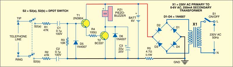

The circuit is divided into two sections: the ringer and the charger. The ringer section is built around transistors T1 and T2 along with a few discrete components. The charger section is built around step-down transformer X1, bridge rectifier comprising diodes D1 through D4, and resistor R5.
When the telephone rings, a 20Hz AC voltage of about 80-90Vrms is superimposed across the telephone line. The resistor-capacitor series circuit (comprising resistors R1, R2, R3 and capacitors C1 and C2) connected across the telephone line provides DC isolation; there is normally a DC voltage of about 48 volts across the telephone line when the line is not in use. Transistor T1 responds to the 20Hz ringing signal by conducting current during each positive half cycle applied to its base. Diode D5 prevents T1 from reverse-bias during the negative half cycle of the ringing signal.

The emitter current of transistor T1 is applied to the base of transistor T2, causing it to saturate and act as a switch. This applies full battery voltage to the bell (piezobuzzer), causing it to ring. The voltage applied to the bell is essentially a 20Hz square wave, which produces a slightly different sound from that produced by pure DC. Diode D6 and capacitor C3 protect transistor T2 from any reverse voltage spikes produced by a collapsing magnetic field of the bell.
In the battery charger circuit, step-down transformer X1 provides isolation from the AC power line while reducing the voltage to about 6Vrms. The output of the bridge rectifier is pulsating DC with about 9V peak, which is applied to the Ni-Cd rechargeable cells through current-limiting resistor R5.
This Ni-Cd charger circuit provides a constant charge current regardless of the battery charge or power line voltage. By limiting the current to not more than one-tenth of the ampere-hour rating of the cells, the charger may be operated for any length of time without damage to the battery due to over-charge.
Working of the circuit is simple. Install the device at a place where you normally cannot hear the telephone bell, such as the lawn. Press switch S2 to enable the device. When someone calls on your telephone, the buzzer produces a ringing sound in parallel with the telephone bell.
The charging circuit can be enabled using switch S1 to charge Ni-Cd rechargeable cells.
Assemble the circuit on a general-purpose PCB and enclose in a suitable cabinet. Fix two terminal connectors on the front side of the cabinet for the telephone line and another two connectors on the rear side of the cabinet for connecting mains power to the primary winding of the transformer. Place the four 1.5V Ni-Cd chargeable cells inside the cabinet. Fix both switches on the front panel of the cabinet to enable/disable the ringer and charger circuit.