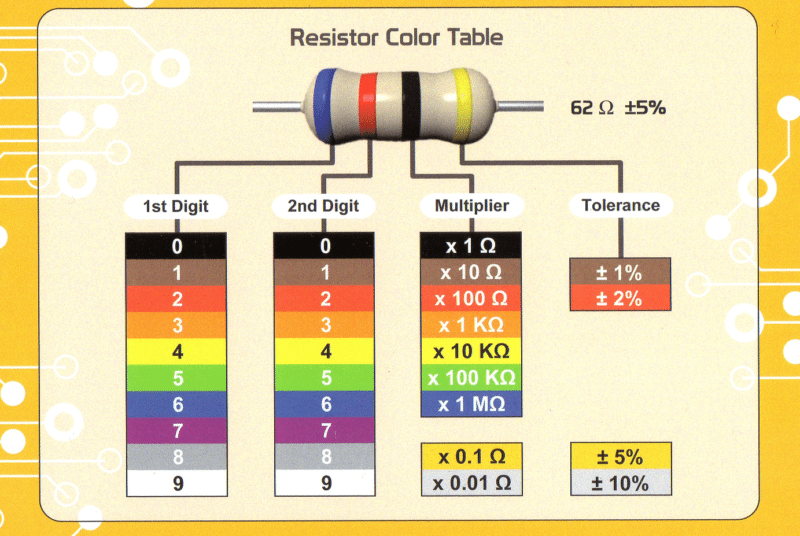
This table will help you with managing resistor color code so that you don’t burn up your circuit due to a wrong resistor.
Right below this image is a little tutorial to help you with the same thing. Have fun!

Getting Started with Resistor Colour Codes
Resistors are available in a range of different resistance values from fractions of an Ohm (Ω) to millions of Ohms.
Values of resistance, tolerance, and wattage rating are generally printed onto the body of the resistor as numbers or letters when the resistor’s body is big enough to read the print, such as large power resistors.
In most cases, when the resistor is small such as a 1/4 W carbon or film type, these specifications will be color-coded. These colored painted bands produce a system of identification generally known as the Resistor Colour Code.
An international resistor color code scheme was developed many years ago as a simple and quick way of identifying a resistor’s ohmic value no matter what its size or condition. It consists of a set of individual colored rings or bands in spectral order representing each digit of the resistor’s value.
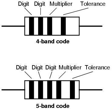
The resistor color code markings are always read one band at a time starting from the left to the right, with the larger width tolerance band oriented to the right side indicating its tolerance.
By matching the color of the first band with its associated number in the digit column of the color chart below the first digit is identified and this represents the first digit of the resistance value.
Calculating the resistance of a resistor based on its color codes involves interpreting the values of the individual color bands. The standard resistor color code uses four bands, and sometimes a fifth band for the tolerance or temperature coefficient. Here are the formulas to calculate resistance:
For Four-Band Resistors:
-
First Band (1st Significant Figure):
- Assign a numerical value to the color of the first band according to the following chart:
- Black: 0, Brown: 1, Red: 2, Orange: 3, Yellow: 4, Green: 5, Blue: 6, Violet: 7, Gray: 8, White: 9.
- Assign a numerical value to the color of the first band according to the following chart:
-
Second Band (2nd Significant Figure):
- Assign a numerical value to the color of the second band using the same chart.
-
Multiplier (Multiplier Multiplier):
- Assign a numerical value to the color of the multiplier band:
- Black: x1, Brown: x10, Red: x100, Orange: x1,000, Yellow: x10,000, Green: x100,000, Blue: x1,000,000, Gold: x0.1, Silver: x0.01.
- Assign a numerical value to the color of the multiplier band:
-
Resistance Calculation:
- Combine the values obtained from the first and second bands and multiply by the multiplier to get the resistance in ohms.
- For example, if the first band is Brown (1), the second band is Black (0), and the multiplier is Red (x100), the resistance is 10 x 100 = 1000 ohms or 1 kilohm.
For Five-Band Resistors (Including Tolerance or Temperature Coefficient):
-
First and Second Bands (1st and 2nd Significant Figures):
- Same as in the four-band system.
-
Multiplier (Multiplier Multiplier):
- Same as in the four-band system.
-
Tolerance Band (Tolerance Percentage):
- Assign a numerical value to the color of the tolerance band:
- Brown: ±1%, Red: ±2%, Gold: ±5%, Silver: ±10%.
- Assign a numerical value to the color of the tolerance band:
-
Resistance Calculation:
- Combine the values obtained from the first and second bands and multiply by the multiplier to get the resistance in ohms.
- The tolerance band indicates the allowable percentage difference from the stated resistance.
These formulas are fundamental for decoding resistor color codes and determining the resistance value of a resistor in an electronic circuit.
Use the below Calculator for Free.
What are Tolerance Codes?
Colors on the resistor like brown, red, green, blue, and violet are used as tolerance codes on 5-band resistors only. The blank (20%) “band” is only used with the “4-band” code (3 colored bands + a blank “band”).

Example: 1
![]()
In this picture, you will see it colored Yellow-Violet-Orange-Gold. This equates to 47 kΩ with a tolerance of +/- 5%.
Example: 2
![]()
Here we have a resistor colored Green-Red-Gold-Silver, which would be 5.2 Ω with a tolerance of +/- 10%.
Example: 3
![]()
A resistor colored White-Violet-Black would be 97 Ω with a tolerance of +/- 20%. When you see only three color bands on a resistor, you know that it is actually a 4-band code with a blank (20%) tolerance band.
Example: 4
![]()
A resistor colored Orange-Orange-Black-Brown-Violet would be 3.3 kΩ with a tolerance of +/- 0.1%.
Example: 5
![]()
A resistor colored Brown-Green-Grey-Silver-Red would be 1.58 Ω with a tolerance of +/- 2%.
Example: 6
![]()
A resistor colored Blue-Brown-Green-Silver-Blue would be 6.15 Ω with a tolerance of +/- 0.25%.
Also Read: Determine The Resistor Values In A Circuit
Common Mistakes in Resistor Color Codes
Understanding resistor color codes is crucial for anyone delving into electronics. However, common mistakes can turn this seemingly straightforward task into a puzzling endeavor.
Let’s explore the common pitfalls encountered when deciphering resistor color codes, and we’ll illustrate these challenges with practical examples.
Misinterpreting the Color Bands:
One of the most frequent errors is misinterpreting the sequence of color bands. Each band represents a specific value, but misreading the order can lead to inaccurate readings. Let’s delve into an example to highlight this issue.
Example:
A resistor with the color sequence Red, Red, Orange, and Gold might be mistakenly read as 22,000 ohms (Red-Red) when it is actually 22,000,000 ohms or 22 megaohms (Red-Red-Orange).
Ignoring Tolerance Bands:
Overlooking the tolerance band is another common mistake. The tolerance band indicates the allowable percentage difference from the stated resistance value. Ignoring this band can result in choosing a resistor with an unacceptable level of tolerance.
Example:
A resistor with the color bands Yellow, Purple, Green, and Silver might appear to be 47 ohms (Yellow-Purple-Green), but if the silver tolerance band is disregarded, the actual tolerance might be wider than expected.
Failing to Account for Temperature Coefficient:
Some resistors come with a fifth band representing the temperature coefficient. Neglecting this band can lead to miscalculations, especially in applications sensitive to temperature changes.
Example:
A resistor with the color bands Brown, Black, Red, Orange, and Brown might be mistaken for 10,000 ohms (Brown-Black-Red), but the temperature coefficient indicates a variation that should be considered.
Mastering resistor color codes requires attention to detail and an understanding of potential pitfalls. By being aware of common mistakes and learning from practical examples, you can confidently navigate the colorful world of resistors in your electronic projects.


Thank you for a nice explaination.
Thank you for your valuable feedback.