


 This RFID Based Access Control System is built around Arduino UNO board, RFID reader module, solenoid lock and a few other components.
RFID is a non-contact, automatic identification technology that uses radio signals to identify, track, sort and detect a variety of objects including people, vehicles, goods and assets without the need for direct contact or line-of-sight contact (as found necessary in bar code technology).
RFID technology can track movement of objects through a network of radio-enabled scanning devices over a distance of several metres. A device called RFID tag, or simply a tag, is a key component of the technology. These are actively used in RFID based access control system implemented in offices all around.
An RFID system typically consists of three key elements:
1. An RFID tag, or transponder, that carries object-identifying data (unique ID code)
2. An RFID tag reader, or transceiver, that reads and writes tag data
3. A back-end database that stores records associated with tag contents
An RFID reader emits a low-level radio frequency magnetic field that energises the tag.
- The tag responds to the reader’s query and announces its presence via radio waves, transmitting its unique identification data.
- This data is decoded by the reader and passed to the local application system via middleware.
- The middleware acts as an interface between the reader and the RFID application system.
- The system then searches and matches the identity code with information stored in the host database or backend system.
In this way, accessibility or authorisation for further processing can be granted or refused, depending on results received by the reader and processed by the database.
RFID based access control System circuit and working
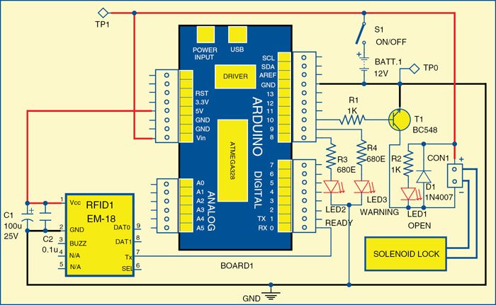
Fig. 1 shows the circuit of RFID based access control using Arduino board. The circuit is built around Arduino UNO board (Board1), RFID reader module (RFID1), solenoid lock and a few other components.
Arduino UNO board
Arduino is an open source electronics prototyping platform based on flexible, easy-to-use hardware and software (called sketch). It is intended for artists, designers, hobbyists and anyone interested in creating interactive objects or environments.
Arduino UNO is a board based on ATmega328 microcontroller. It consists of 14 digital input/output pins, six analogue inputs, a USB connection for programming the on-board microcontroller, power jack, an ICSP header and a reset button. It is operated with a 16MHz crystal oscillator and contains everything needed to support the microcontroller. It is very easy to use as the user simply needs to connect it to a computer with a USB cable or power it with an AC-to-DC adaptor or battery to get started. The microcontroller on the board is programmed using Arduino programming language and Arduino development environment.
Pin 0 (RX) of Board1 is connected to pin 7 (TX) of RFID1. Pin 10 of the board is connected to solenoid driver transistor T1 through base resistor R1. When pin 10 goes high, T1 conducts and solenoid is activated, which means lock is opened.
RFID reader module
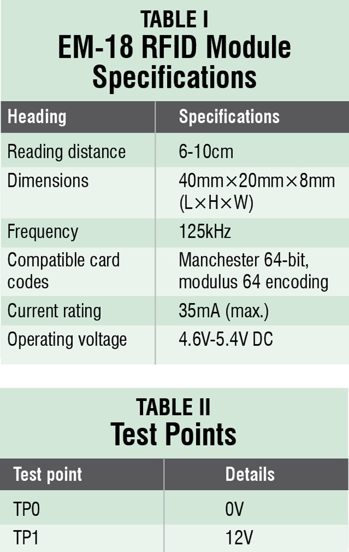
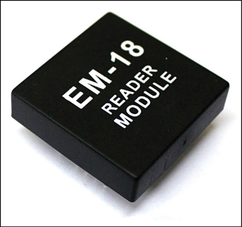
In this project, we used EM-18 RFID reader module (Fig. 2) operating at 125kHz. The module comes with an on-chip antenna and can be powered with a 5V power supply. The transmit pin (TX) of the module should be connected to receive pin (RX) of Arduino UNO board. Some specifications of the module are listed in Table I.
RFID tag
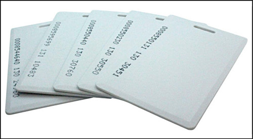
An RFID tag is a smooth card of credit-card size (Fig. 3), which is read by an RFID reader. It works at 125kHz and comes with a unique 32-bit ID. Normally, each tag has a unique ID number which cannot be changed. You can find out its unique ID through software.
Software
The software for this project is written in Arduino programming language. The Arduino UNO is programmed using Arduino IDE software. Atmega328 on Arduino UNO comes with a boot loader that allows you to upload new code to it without the use of external hardware programmer. It communicates using STK500 protocol.
You can also bypass the boot loader and program the microcontroller through in-circuit serial programming (ICSP) header, but with boot loader the programming is quick and easy.
Download PCB Layout and component layout PDFs: click here
Download source code: click here
There are two sketch software codes for this application: ReadTag.ino for reading the tag’s unique ID and AccessControl.ino for the main application.
Reading tag ID
To read the tag’s unique ID, first you need to upload ReadTag.ino sketch into Arduino board by following the steps given below:
1. Connect TX pin of RFID1 to RX pin of Board1 as shown in the Fig. 1
2. Launch Arduino IDE. Connect Board1 to your PC and select the correct serial COM port and Board from Tools menu. Open ReadTag.ino sketch and compile it using Arduino IDE.
3. Burn ReadTag.ino sketch into the microcontroller in Arduino board
4. Open Serial Monitor from Tools menu in Arduino IDE
5. Hold RFID tag close to RFID1
6. Note down the tag ID shown on the Serial Monitor window. This ID will be used in the sketch later in the main application
Programming the main application
The main application of this project is access control system. So we need to upload AccessControl.ino sketch into the microcontroller in Board1. Note that before uploading the sketch into the microcontroller, you should remove the RFID reader module from the circuit. For programming:
1. Open the AccessControl.ino sketch from the Arduino IDE
2. Change the tag ID in AccessControl.ino sketch with the ID you have noted down earlier
3. Connect the Arduino board (Board1) with the PC
4. Upload the sketch into the board
If uploading is successful, you will see the glowing of LED2. It means the system is ready to read the tag. Now, bring the tag near RFID1 reader. If tag ID matches with the ID in the code, solenoid lock will open for five seconds. It closes automatically after five seconds.
Glowing of LED1 indicates that the lock is open.
Glowing of warning LED3 means that you are using the wrong tag.
Construction and testing
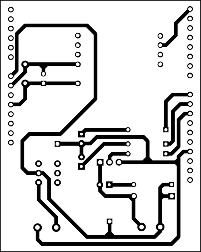
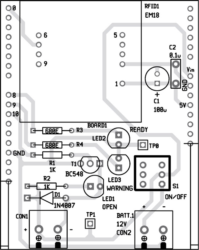
A single-side PCB (Arduino shield type) for access control is shown in Fig. 4 and its component layout in Fig. 5. Assemble the circuit on recommended PCB to save time and minimise assembly errors. Double-check for any overlooked error.
To test the circuit for proper functioning, verify correct 12V supply for the circuit at TP1 with respect to TP0.
Thank you.
You are most welcome.
Can i use RM6300
how can i add multiple tag id ??
I want to know that too. This is the reason i come here. 😀
Just edit its ID Reader and scanner ID multiple time in Source code where conditions applied
Can i integrate a gsm module?
iam not an engineering student,is there any one can help me to make a rfid based shopping trolli using aurdino?
contact me on my mail id .pleas urgent
Hi there,
Will it be possible to add an other lock with an other RFID tag?
I need a source code for this project
The source code is present in the article itself.
unable to download the source code. it will just get redirected to a blank page
Kindly refresh the page and redownload
Sir,
In the Table I
Reading Distance is mentioned as 6-10cm
Why can’t we use below 6cm?
It should be up to 10cm.