


When it comes to security, RFID card-based digital locks are more reliable than key-based mechanical locks since they cannot be easily broken. Also, they are Contactless Lock, therefore, some hotels across the world have adopted this technology.
However, there is a danger of passwords getting leaked, allowing anyone to infringe on a person’s privacy.
So in today’s project, we will make an contactless RFID lock for hotel rooms that has an additional feature of temporarily storing a person’s hotel check-in and check-out details. This means that the card will only work for that particular person up to the designated hotel stay schedule.
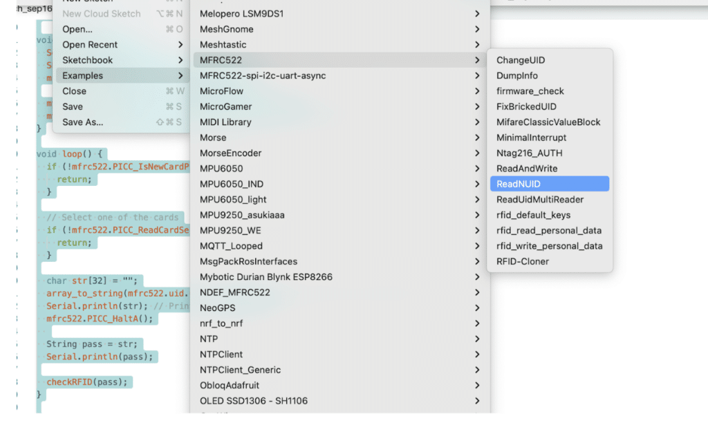
First, we need to install libraries to Arduino IDE. To install the required library, go to Arduino IDE and open the library manager. Type MFRC522 in the search bar and select install. Now you can begin coding.
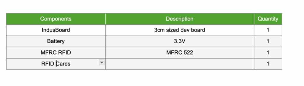
Bill of Material
Besides MFRC522, also include the library Servo in the code. While MFRC522.h enables the RFID reader module to read the RFID card, Servo.h equips the lock with a servo motor mechanism.

Next in the setup function, first, initialize the serial port for debugging to obtain the RFID number. Then initialize the SPI communication with the RFID module and set the servo pin number to drive the servo motor.
After this, create a loop function to read the RFID UUID number. Then convert the RFID UUID number to a string and check whether it matches with the correct UUID number. If yes, then the servo motor automatically gets activated for unlocking the door.
Contactless RFID Lock – Code
First uplaod the UUID reader code found in example of library. Get the UUID in serial monitor

Now in code first declare the servo motor pin for lock and unlock and then
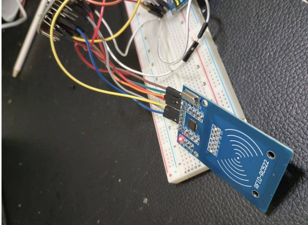
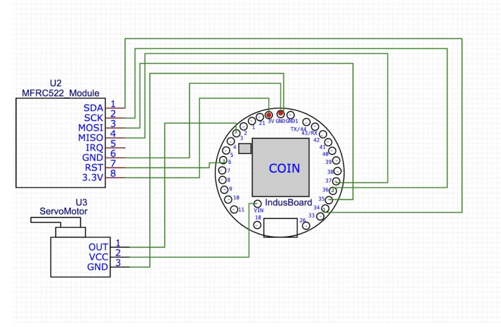
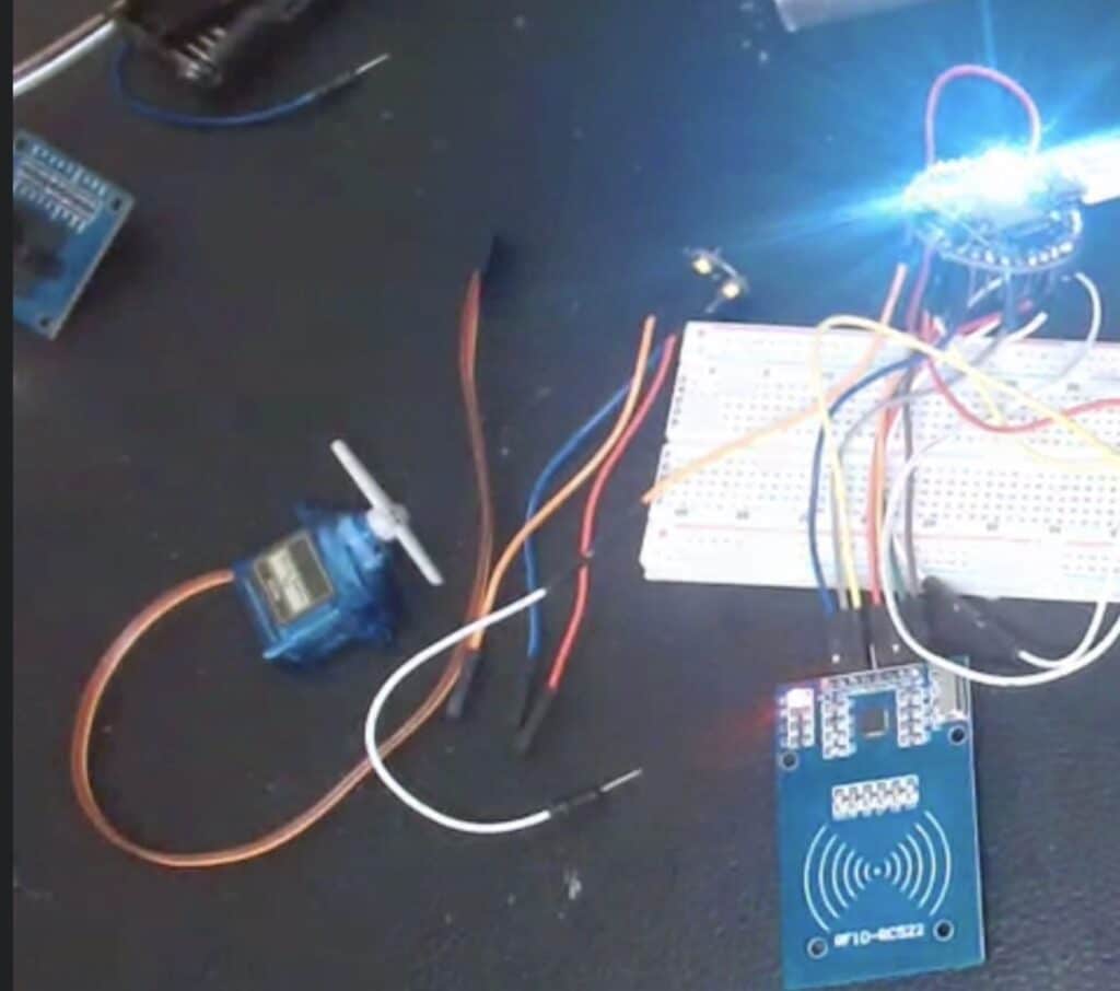
Connection
any pin on the IndusBoard Coin can be configured as SPI here we have used default one on IndusBoard
Testing
- Procedure:
- Power on the IndusBoard Coin.
- Observe if the servo motor moves to the initial locked position (0 degrees).
- Check the Serial Monitor (at 9600 baud) for any initialization messages.
- Expected Result:
- The servo motor should move to the locked position.
- The Serial Monitor should show the RFID reader is ready and no errors.
Test Case 2: Correct RFID Tag Detection
- Objective: Validate that the servo motor unlocks when a correct RFID tag is detected.
- Procedure:
- Bring the correct RFID tag (the one matching the UID in your code) close to the RFID reader.
- Observe the Serial Monitor for the detected RFID UID.
- Check if the servo motor unlocks (moves to 90 degrees) and stays unlocked for 5 seconds.
- After 5 seconds, check if the servo motor locks again (moves back to 0 degrees).
- Expected Result:
- The correct RFID UID should be printed on the Serial Monitor.
- The servo should move to 90 degrees (unlock) and return to 0 degrees (lock) after 5 seconds.
Test Case 3: Incorrect RFID Tag Detection
- Objective: Ensure the system remains locked when an incorrect RFID tag is detected.
- Procedure:
- Bring an incorrect RFID tag (one with a UID that doesn’t match the correct one in your code) close to the RFID reader.
- Observe the Serial Monitor for the detected RFID UID.
- Check the position of the servo motor to ensure it remains locked (at 0 degrees).
- Expected Result:
- The incorrect RFID UID should be printed on the Serial Monitor with a “Wrong Password: Locked!” message.
- The servo motor should not move and should stay locked (at 0 degrees).
Test Case 4: Servo Motor Responsiveness
- Objective: Validate that the servo motor responds appropriately to RFID detection events.
- Procedure:
- Alternate between scanning a correct RFID tag and an incorrect one.
- Observe if the servo motor unlocks and locks accordingly.
- Expected Result:
- For correct RFID tags, the servo motor should unlock for 5 seconds and then lock.
- For incorrect RFID tags, the servo motor should remain locked.
Test Case 5: System Stability Over Time
- Objective: Verify that the system operates reliably over an extended period.
- Procedure:
- Continuously test the system over a period of 30 minutes to an hour by scanning both correct and incorrect RFID tags intermittently.
- Monitor the Serial Monitor and servo motor to check for any unexpected behavior or failures.
- Expected Result:
- The system should consistently read RFID tags and control the servo motor without any malfunctions or crashes over the test period.
Troubleshooting
- RFID Reader Not Working:
- Double-check the wiring of the MFRC522 module.
- Ensure the correct SS_PIN and RST_PIN are set in the code.
- Confirm that the RFID tags being used are functional.
- Servo Motor Not Responding:
- Verify that the servo is properly connected to pin 3.
- Make sure the power supply is adequate for the servo.
- Test the servo with simple code (e.g., Servo sweep example) to ensure it functions correctly.
- Incorrect RFID Readings:
- Check the RFID UID printed on the Serial Monitor and confirm it matches the one in the code.
- Ensure the RFID tag is within range of the reader.
By following this testing guide, you can systematically check if your RFID Lock Project using the IndusBoard Coin and servo motor functions as expected.
