


 Red-green-blue (RGB) multi-colour bulbs available in the market are expensive as these are based on a microcontroller. The program for the microcontroller is difficult to understand. Here is a simple and inexpensive circuit for an RGB bulb using 555 timer.
An RGB bulb is made up of three individual LEDs: red, green and blue. The intensities of these LEDs are varied to generate lights of different colours or shades.
The main objective of this project is to produce different light colours with the help of NE555 timer IC. The author’s prototype is shown in Fig. 1.

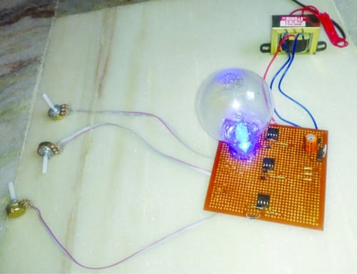
Fig. 1: Author’s prototype

RGB bulb using 555 timer circuit
Circuit diagram of the RGB bulb using 555 timer is shown in Fig. 2. It is built around 230V AC primary to 12V-0-12V, 500mA secondary transformer (X1), a 5V regulator IC 7805 (IC1), three NE555 timers (IC2 through IC4), red, green and blue LEDs (LED1 through LED3), and a few other components.

Fig. 2: Circuit diagram for the RGB bulb using 555 timer
To derive regulated 5V for the main circuit, 230V AC mains supply is stepped down by transformer X1, rectified by a full-wave rectifier comprising diodes D1 and D2 (1N4007), filtered by capacitor C1 and fed to IC1.
Three similar astable multivibrators are built around NE555 ICs (IC2, IC3 and IC4), each for red, green and blue LEDs, respectively. These use a 1-kilo-ohm resistor, a 10-kilo-ohm potmeter and a 0.1µF capacitor as R-C timing components.
Pins 1 and 8 of each NE555 are connected to ground and +5V, respectively. Reset input (pin 4) is also connected to +5V. Control voltage input (pin 5) is connected to ground through 0.01µF capacitor. 1-kilo-ohm resistor is connected between +5V and discharge input (pin 7) of NE555. 1N4148 diodes are connected back to back with pin 7 and two fixed terminals of 10-kilo-ohm potmeter to maintain 50% duty cycle. The third slider terminal of the potmeter is connected to 0.1µF capacitor and threshold input (pin 6). Trigger input (pin 2) is shorted with pin 6 to complete the astable multivibrator configuration. Red, green and blue LEDs (LED1, LED2 and LED3, respectively) are connected to the corresponding output pin 3 of each NE555 in current-sinking mode with a 220-ohm current-limiting resistor.
The LED intensity is varied using pulse-width-modulated (PWM) signal generated by NE555 IC. The frequency of astable multivibrators can be varied from 680Hz to 4.8kHz depending on the values of their timing components.
For instance, the frequency of the astable multivibrator built around IC2 is:
F=1/T=1.44/{(R1+2VR1)xC3}
Circuit operation
All the three astable multivibrators operate in a similar way. Potmeters are used to vary the PWM output signal.
Let us see how the astable multivibrator circuit generates PWM signal: When the output of IC2 (NE555) is high, capacitor C3 charges through 1-kilo-ohm resistor, diode D3 and part of VR1 (say, VR1A). When capacitor voltage reaches 2/3Vcc, the output of IC2 goes low.
Now capacitor C3 discharges through the other part of VR1 (say, VR1B) and D4 to 1/3Vcc.
So sliding VR1 towards left decreases VR1A value, and hence charging time, ‘on’ time and duty cycle. At the same time, VR1B increases, which increases the discharging time as well as ‘off’ time.
On the other hand, turning VR1 towards the right position increases VR1A, and hence the charging time, ‘on’ time and pulse-width. But as VR1B is decreased, ‘off’ time decreases too. Thus, pulse-width can be varied by sliding VR1 towards its sides. When this PWM signal is applied to the LED, the average voltage applied to the LED varies. This varies its intensity and brightness. Thus the three potmeters vary the brightness of red, green and blue LEDs.
By varying a potmeter from minimum to maximum, the colour intensity of the respective LED varies from 0% to 100%. For example, if VR3 is turned towards maximum value, the blue LED intensity become almost nil. Now varying VR1 and VR2 will produce different colours like red, green, yellow, lime, orange, and various shades of green and red.
Similarly, set VR2 to maximum value in order to turn off the green LED. Then vary VR1 and VR3. This will generate red, blue, magenta, violet, and various shades of red and blue. Thus, by varying these three potmeters, many different colours can be generated. If the three LEDs are carefully placed inside an incandescent bulb glass housing, it becomes an RGB bulb!
Construction and testing
A PCB layout of the RGB bulb using 555 timer is shown in Fig. 3 and its components layout in Fig. 4. After assembling the circuit on the PCB, enclose it in a suitable plastic box. Affix red, green and blue LEDs inside an incandescent bulb housing using glue.
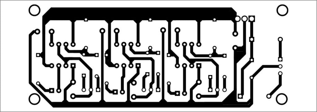
Fig. 3: PCB layout of the RGB bulb using 555 timer
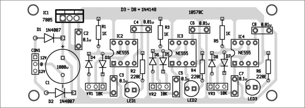
Fig. 4: Components layout for the PCB
Download PCB and component layout PDFs: click here


ATTiny 2313 or STM32F030 costs almost the same price as 3 * 555, but adding the bunch of diodes, caps, 7805, having in mind, that PCB is far bigger, than that in case of MCU usage, I would stay with MCU+3*MOSFET. This is nice scheme for education purposes, but not really practical.
What kind of circuit simulator youu use?
We have not used circuit simulator but actually tested the circuit wired on a breadboard. However, you can also test it with simulation software such as LTSpice, PSpice, etc.
I need PCB and components. Please what is cost this.
For PCB, components and price details please contact on [email protected]
I am new to this, I am having difficulty understanding the diagram and connecting the components to the bredboard. Any help would be appreciated.
Kindly contact us at [email protected]