


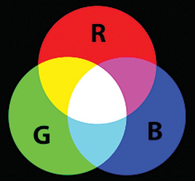
 Presented here is a red, green and blue or RGB colour generator using AT89C2051 microcontroller (MCU). This is a simple and low-cost circuit for a multiple colour generator that can be built easily with a few additional components. The main objective of the project is to generate multiple colours from RGB primary colours as used in television displays, computer monitors and other colour displays for commercial applications like LED projectors. The concept of primary colour mixing is shown in Fig. 1.
 Additive mixing of red and green lights produces shades of yellow, orange or brown. Mixing green and blue produces shades of cyan, whereas mixing red and blue produces shades of purple including magenta. Mixing nominally equal proportions of the three primaries results in shades of grey or white; colour space that is generated is called an RGB colour space.
RGB colour generator circuit
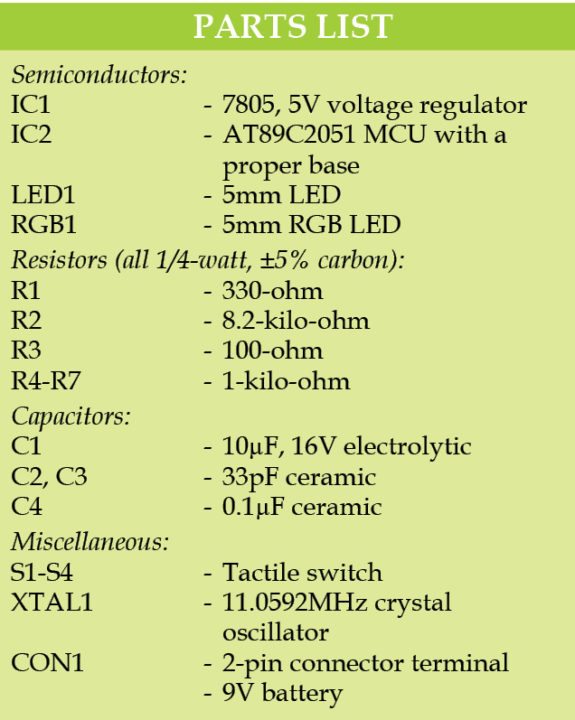
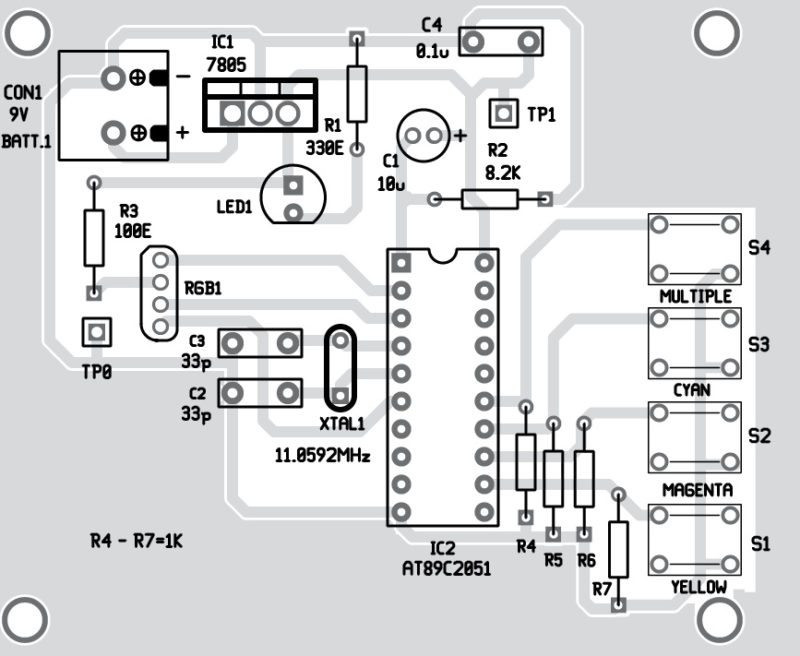
The circuit diagram for the multiple colour generator is shown in Fig. 2. The circuit requires a 9V battery, 7805 voltage regulator (IC1), Atmel AT89C2051 MCU (IC2) and a few other components. The 20-pin MCU performs the operation of multiple colour generation from RGB primary colours on pressing switches S1 through S4. In this project, we have used the concept of pulse width modulation (PWM) to change the colours of the RGB LED.

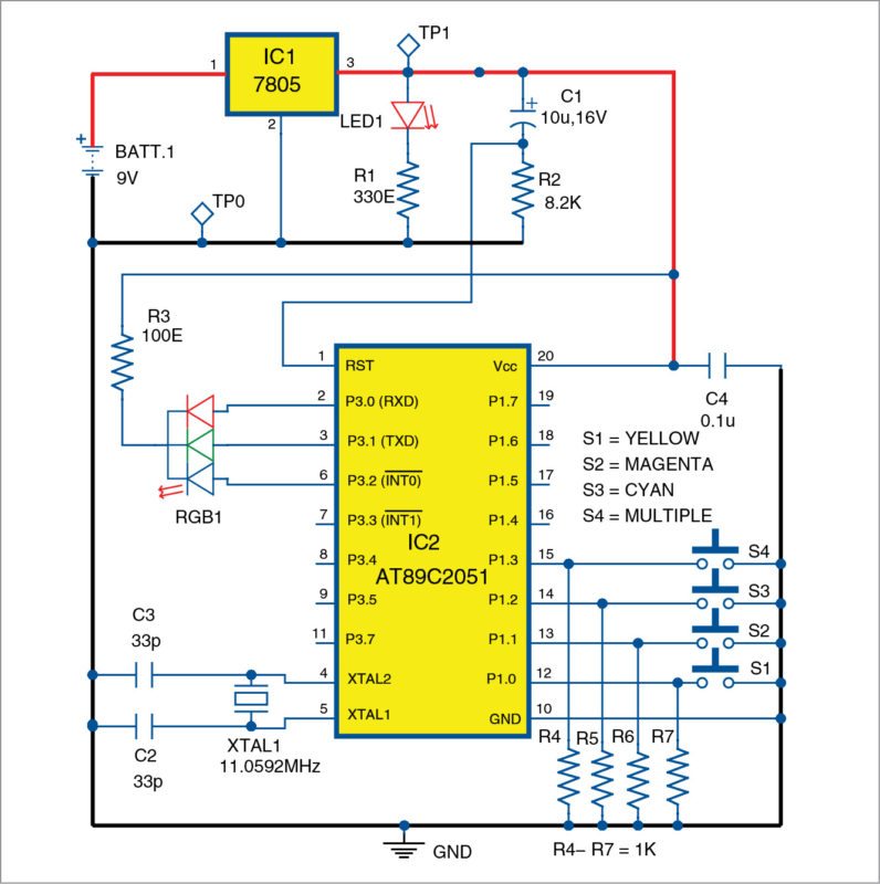
Initially, the circuit is powered by a +9V supply, which is connected to IC1 to maintain a constant +5V at its output. This constant output is fed to the MCU circuit. Port3 of IC2 is used to drive common-anode RGB LED, with P3.0 connected to red pin, P3.1 to green pin and P3.2 to blue pin of the RGB LED. Port1 is connected to the four tactile switches S1 through S4 for producing multiple colours.
 When the circuit is switched on, red colour of the RGB LED glows for a preprogrammed time interval of three seconds. It then switches off for three seconds. This is followed by green and blue colours switching on and off in a similar manner and for the same time periods.

Now, when we press switch S1, we get yellow colour (red+green), and if we press switch S2, we get magenta (red+blue). If we press switch S3, we get cyan (blue+green), and if we press switch S4, we get multiple colours with the help of PWM technique.
Software
The software is written in embedded C language and compiled using Keilµvision 4 version compiler. It contains simple switch statements to produce different colours from primary colours. We have used Topwin 6 software to burn the hex code into the MCU using a Universal Topwin programmer board.
Construction and testing
A single side PCB of the circuit is shown in Fig. 3 and its component layout in Fig. 4. Assemble the circuit on the PCB as it minimises time and assembly errors. Carefully assemble the components and double-check for any error(s). Use a proper IC base for the MCU.
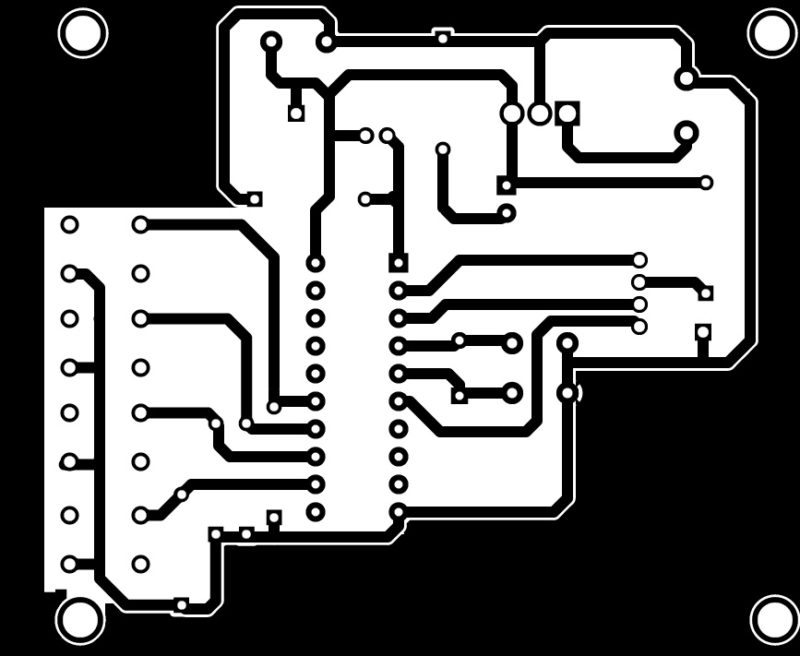
Download PCB and component layout PDFs: click here
Download source code: click here
CON1 is a 2-pin connector used to connect a 9V battery.
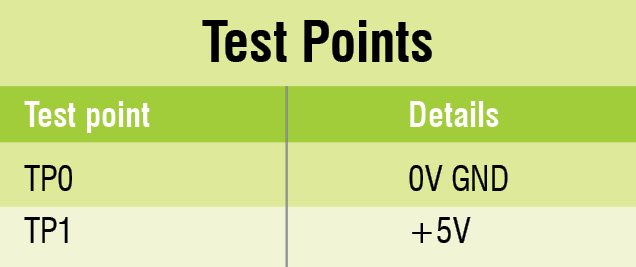
For troubleshooting, verify the voltages listed in the test points table.
The article was published in June 2016, and has been updated recently.
Feel interested? Check out other electronics projects.


Please correct the LED connection Cathode side of LED connected with + Positive.
Share basic circuits
sir plise softwer link
Hi Bapi, we have replied via email.