


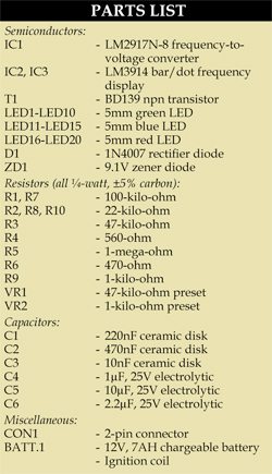
 An efficient way to measure the RPM of a vehicle is through its ignition pulses. RPM of a vehicle is directly proportional to the rate of its ignition pulses. An ignition coil (also called spark coil) is an induction coil in an automobile’s ignition system that transforms the battery’s low voltage to the thousands of volts needed to create an electric spark in the spark plugs for igniting the fuel. Here we measure the rate of ignition pulses with a sensor system attached to the spark coil and thus indicate the RPM using a bar graph comprising 20 LEDs.
Circuit and working
Fig. 1 shows the circuit for RPM meter. The circuit is built around frequency-to-voltage converter LM2917N-8 (IC1), bar display drivers LM3914 (IC2 and IC3), 20 LEDs (LED1 through LED20) and some other components.

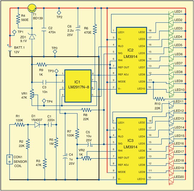
The circuit has three stages—pulse detection, frequency-to-voltage conversion and display of voltage by the LED bar graph. To sense the pulses from the ignition coil, 18SWG PVC-covered household wire is wrapped around LT side of the ignition coil. The number of turns should be around 50. Induction pulses from the sensor coil must be reduced, rectified and filtered. Resistor R1 reduces their voltage level, diode D1 rectifies them and capacitor C1 filters them.
These filtered pulses are fed at pin 1 of frequency-to-voltage converter IC1. Voltage output corresponding to the frequency of pulses is available at pin 4 of IC1. The level of this output voltage can be controlled by preset VR1. LM2917N-8 (IC1) is available in 8-pin and 14-pin versions; we have used 8-pin version here. The output of IC1 is fed at pins 5 of IC2 and IC3 through a filter formed by resistor R8 and capacitor C5. This filter removes any variations in the output and provides stable reading. IC2 and IC3 are connected to each other in cascade mode. Pin 9 of both these ICs are held at high voltage to select bar mode.

The number of LEDs glowing will be directly proportional to the input voltage at pin 5, which, in turn, is dependent on the frequency of pulses. This implies that the number of LEDs glowing will be in accordance with the RPM of the vehicle.
The overall system can be calibrated as per one’s liking (see last paragraph). We calibrated it such that each LED indicates about 1200 revolutions. LEDs should be of three different colours so that these can indicate normal (green), medium (blue) and high (red) speed zones.
Power supply is taken from the vehicle’s battery. Car battery’s 12V DC is reduced to 9V so that the display’s brightness remains the same, irrespective of whether the battery is less charged or overcharged.
Construction and testing
An actual-size, single-side PCB for the RPM meter is shown in Fig. 2 and its component layout in Fig. 3. After assembling the circuit on PCB, enclose it in a suitable box. Use two-pin connectors on the PCB for connecting the sensor coil and the battery terminals.
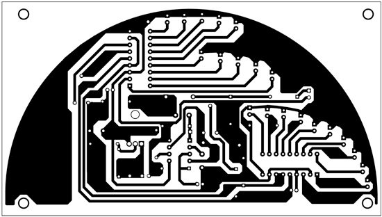
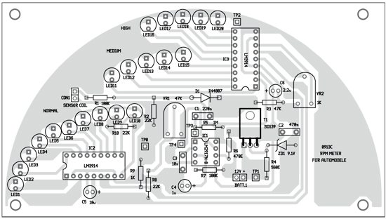
Download PCB and component layout PDFs: click here
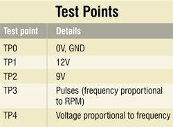
To check the circuit for proper functioning, verify input supply at TP1 with respect to TP0. This supply is reduced to 9 V, which can be checked at TP2. Check the sensed pulses from the ignition coil at TP3 using an oscilloscope. The voltage at TP4 will vary as per frequency of pulses.
To calibrate the system, as we did, use a function generator. Give 20Hz signal at TP3 and, using preset VR1, set its amplitude such that only LED1 glows. When you increase the frequency, you will see more LEDs glowing. Your system is now ready to use. Use preset VR2 to define the frequency range for each LED bar display.
The author is a regular contributor to EFY.

Hello Sir , May i use LM2917n-14 pin IC instead of LM2917n-8 pin IC.
Either version will work the same. It is in the text mentioning 8 and 14 pin chips. Just have to be sure the correct pin out is maintained. Modify the traces of PCB to match chip version, and you will have to move some traces around to make room for the larger chip. But why? Just get an 8 pin chip and follow this design.
No problem using a 14 pin version if you adjust the circuit board appropriately. But why? Both chips do the same thing. And you have the 8 pin layout already, here. I built a batch of controllers for wind turbines some years back using both 8 and 14 pin chips. The 8 pin version was just a lot easier to work around.
Sir, I am able to procure LM2907 but not LM2917. Even the datasheet are the same. Can I use LM2907?
Yes you can use LM2907 in place of LM2917 as there parameters
are same in datasheet.