 Cigarette lighter sockets available on the dashboards of some vehicles act as a heat source to light cigarettes. Besides, these can power electronic gadgets like tablets, laptops, portable video players, MP3 players and cellphones. Some of these devices can be plugged directly into the cigarette lighter socket, while others may need an inverter (DC-AC converter).
However, using the cigarette lighter socket to power electronic gadgets while the car engine is not running may drain the car’s battery. This circuit lets you use the cigarette lighter socket to power your electronic gadgets without the fear of draining the car’s battery.
The circuit supplies power to electronic devices with low-voltage protection mechanism. A moulded cigarette lighter socket extension cable (refer Fig.3) is necessary for the circuit. Cut the extension cable and solder its leads to the input of the circuit (J1). The circuit receives 12V DC at J1 through polarity protection diode D1.

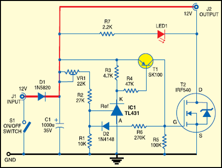
As shown in Fig.1, the heart of the circuit is IC TL431 (IC1)—a voltage regulator wired as a comparator. When the voltage at the reference terminal (Ref) of IC1 exceeds 2.5 V , its cathode (K) goes low, which provides base emitter biasing of transistor T1. Transistor T1 provides regenerative feedback via the combination of resistor R6 and diode D2 to turn on transistor T2, which is an n-channel power MOSFET. As a result, the DC supply from input pin J1 is routed to the output load connected at socket J2.

However, if the battery voltage drops below 10V, the reference terminal voltage of IC1 falls below 2.5V and its cathode goes high. Transistor T1 unbiases to turn off transistor T2 and the output load disconnects to prevent deep discharge of the storage battery. The red LED (LED1) is used as a simple output-power status indicator. SPST toggle switch S1 is the power-on/ off-cum-reset switch. For testing the circuit, apply 12V DC to input point J1 and adjust trimmer VR1 (22-kilo-ohm) such that LED1 lights up and the output voltage is available at J2. Recheck the calibration to ensure that the output supply is disabled when the input voltage falls to a value of about 10V DC.

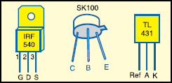
IC1 is a three-terminal adjustable shunt regulator. Its output voltage may be set at any level greater than 2.5V (VRef) and up to 3.6V by selecting resistors R1 and R2 that act as a voltage-divider network. T2 is a general-purpose n-channel power MOSFET. Any MOSFET with similar characteristics can also be used in place of T2. Use a heat sink for T2 to allow heat dissipation.
After construction, enclose the circuit in a small metallic or plastic box with holes to mount the power switch (S1) and indicator (LED1). Output jack J2 should match with the appliance to be used.


