


 Presented here is an Arduino-based dish antenna angle controller to align the position of a satellite dish antenna by setting azimuth and elevation angles. The dish antenna should always point to a specific satellite in space to receive maximum signal. Even a slight deviation from the point may reduce signal strength.
Azimuth and elevation angles are set using input switches, as explained in the next section. Once these values are set, the dish antenna automatically moves in vertical and horizontal directions with the help of two DC geared motors.
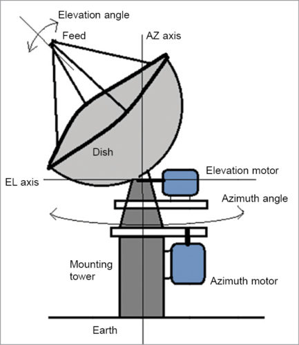
Fig. 1 shows the diagram of the antenna system along with the positions of azimuth (AZ axis) and elevation motors (EL axis).

Circuit and working
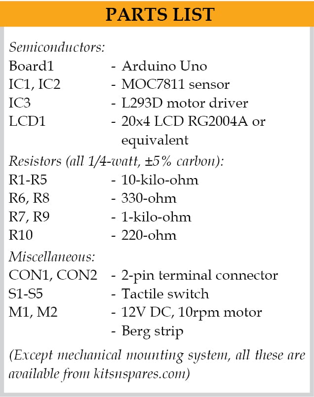
The circuit diagram of the satellite dish antenna angle controller using Arduino is shown in Fig. 2. It is built around Arduino Uno (Board1), two slotted opto-interrupter sensors MOC7811 (IC1 and IC2), motor driver L293D (IC3), 20×4 liquid crystal display (LCD1), two 12V DC, 10rpm motors (M1 and M21) and a few other components.
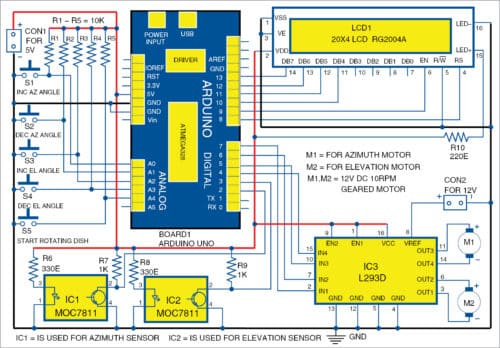
Each sensor circuit is built around MOC7811 having an internal IR LED and phototransistor. Both sensor circuits for elevation and azimuth angles are identical. Internal IR LED is given 5V supply through 330-ohm current-limiting resistors (R6 and R8), and photo-transistor is connected to switch configuration using external 1-kilo-ohm resistors (R7 and R9).
IR light beams continuously fall on the phototransistors. Sensor outputs are taken from collectors (pin 2) of the phototransistors.
Both sensor outputs (from IC1 and IC2) are connected to digital I/O pins 2 and 3 of Arduino Uno, respectively. Pins A0 through A4 are connected to 5V through resistors R1 through R5, respectively. Switches S1 through S5 are connected such that when a switch is pressed, logic 0 is given as input to Arduino Uno.
Digital pins 8 and 9 of Arduino Uno are connected to LCD1 control pins RS and EN, respectively. LCD1 data pins DB4 through DB7 are connected to digital pins 10, 11, 12 and 13 of Arduino Uno. R/W pin of LCD1 is connected to ground to make it write enable. Digital pins 4, 5, 6 and 7 of Arduino Uno are connected to input pins of L293D (IC3). The motors are connected to output pins of L293D. Arduino Uno drives the two DC motors (M1 and M2) through L293D.
The whole circuit works on 5V DC supply. Arduino Uno can be given 5V regulated supply on its 5V pin. A separate 12V supply is given to pin 8 of L293D for the motor supply.
Actual controlling of the dish antenna angle controller is done using software (dish_contr.ino) written in Arduino programming language and compiled using Arduino IDE software.
Download source folder: click here
Demonstration model
Fig. 3 shows the proposed satellite dish antenna mounting system for a demonstration model. There are two DC geared motors rated at 12V DC with 10rpm speed. The motor that rotates the dish antenna in horizontal plane is azimuth motor 1 (AZ motor or M1), and the one that rotates it in vertical plane is elevation motor 2 (EL motor or M2).
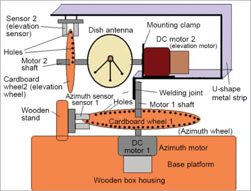
Two opto-interrupter sensors (MOC7811) are used to provide feedback of motor angular positions. Encoding wheels are attached to the shaft of each motor. Each encoding wheel has holes (say, 6mm dia) at 10°, 20°, 30° and so on, up to 350°. The arrangement is done in such a way that, as the motor rotates, the wheel also rotates and its holes pass through the slotted gap of MOC7811 sensor. Interruption of IR light by each hole generates one pulse per 10° of motor rotation. The proposed arrangement of the mechanical assembly is explained step-by-step below.
- The entire system is set up in a wooden box that houses the circuit and also serves as the base or platform for demonstration of the model.
- Azimuth motor (M1) is fixed inside the wooden box using bolt and screws. Encoding cardboard wheel 1 (azimuth) with 35 holes is attached to its shaft.
- Azimuth sensor 1 (IC1) is also mounted vertically using a small wooden stand on the same wooden platform such that holes of azimuth encoding wheel 1 (azimuth) pass through the slotted gap of azimuth sensor 1.
- A U-shaped metal strip of around 5cm is directly welded to the shaft of elevation motor (M2). One arm of the U-shaped metal strip is longer than the other arm.
- Elevation sensor 2 (IC2) is fixed at the end of the longer arm of this metal strip. Elevation motor 2 is mounted on the shorter arm using mounting clamp and screws.
- A dish antenna made up of cardboard and aluminium foil is directly fixed on the shaft of elevation motor 2. Encoding wheel 2 (elevation wheel) with seven holes is also attached on the shaft of DC motor 2.
- This encoding elevation wheel 2 is fixed in such a way that holes of the wheel pass through the slotted gap of elevation sensor 2.
Working of demonstration model
Initially, set the angles of both the motors to 0°. This means, the dish antenna has a 0° azimuth angle and 0° elevation angle. Azimuth angle can be set from 0° to 350° in steps of 10° using pushbutton switches S1 and S2.
Then, set elevation angle from 0° to 70° in steps of 10° using S3 and S4.
When both angles are set, press start pushbutton S5 to rotate the dish antenna. Automatically, azimuth motor 1 will start rotating to set the dish antenna in azimuth angle. As AZ motor 1 rotates, encoding wheel 1 will also rotate and its holes will pass through the gap of sensor 1.
The sensor generates pulses that give feedback of the motor’s angular position. The motor rotates till the set angle is reached. If set angle is more than the angle of initial position motor 1, it will rotate in clock-wise direction, and if set angle is less than the angle of initial position motor 1, it will rotate in counter-clock-wise direction.
Next, elevation motor 2 will start rotating automatically. It will rotate the dish antenna as well as elevation encoding wheel 2 till set angle is reached.
Once sensor outputs match the entered values of azimuth and elevation angles, both motors will stop rotating and dish antenna will remain in that position. Thus, the dish antenna will attain the desired angular position in azimuth and elevation planes.
If you want to change the dish antenna position (like tracking another satellite), change azimuth and elevation angles by entering new values using input switches to move the dish antenna to a new position.
Operation
Initially, when power is switched on, LCD1 will show AZ angle and set EL angle as 0°. Set AZ angle by pressing AZ angle inc or dec buttons, and EL angle by pressing inc or dec buttons. Every time a button is pressed, the angle changes by 10°.
After setting the angles, press S5. Motor 1 will rotate, followed by motor 2. LCD1 will display the values of azimuth and elevation angles. When the dish antenna attains the desired position, LCD1 will show the set dish position.
Ashutosh M. Bhatt is M.Tech in embedded systems. Currently, he is lecturer of electronics and radio engineering at Government Polytechnic, Jamnagar, Gujarat.

Hello Ashutosh M. Bhatt,
Thank you for the description and realisation. A very good job.
Your project will serve as the basis for my future amateur radio satellite tracking station.
F6ARZ
Alain LEBLANC
Thank you for your feedback.
Please send the proteus connection with zip file
Dear Cofnan,
For proteus connection with ZIP file refer link below.
https://drive.google.com/file/d/1z0SVZYIi2wn6XZHw9za3MsSiRM4YsKxP/view?usp=sharing
Regards