 Presented here is an extra-high-tension (EHT) power supply capable of delivering variable DC voltage from about 100 V to 5 kV with load current up to 500 mA. One way of obtaining such high DC voltages capable of delivering load currents up to a few amperes is to control the AC input voltage to the primary of a power transformer using high-power SCRs connected back to back. The same principle is used in designing this power supply.
The most important design aspect of this circuit is the generation of SCR triggering pulses synchronised with the input sine wave. This ensures that the SCRs used for controlling the positive and negative halves of the sine wave can be switched on at the same angle determined by the intersection of a synchronised sawtooth wave and DC control voltage (explained later).
This basic circuit can be extended to higher values of voltages and load currents, by using suitably rated SCRs and power transformers.
Circuit and working
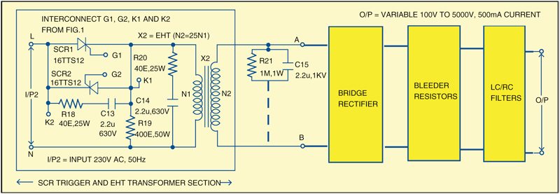
The circuit of SCR-controlled EHT power supply is divided into two sections: pulse generator and EHT generator. The pulse generator circuit is shown in Fig. 1 and EHT generator circuit in Fig. 2.
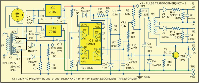
The pulse generator section generates SCR triggering pulses synchronised with the input sine wave. It is built around transformer X1, bridge rectifier BR1, quad operational amplifier LM324 (IC1), +15V voltage regulator 7815 (IC2), -15V voltage regulator 7915 (IC3), pulse transformer (X3), npn transistor SL100 (T1) and a few discrete components.
Transformer X1 is a special type of step-down transformer that has two secondary windings, viz, 20V-0-20V, 500 mA and 18V-0-18V, 500 mA, respectively. The power supply for circuit operation is built using 20V-0-20V secondary winding of transformer X1, followed by rectifier BR1. Capacitors C7 and C8 are used to filter positive and negative ripples, respectively. IC2 is a +15V regulator, while IC3 is a -15V regulator. Capacitors C9, C10, C11 and C12 are decoupling capacitors used to decouple DC power supplies for high-frequency noise, if any, present on the DC power supply line.
Working of the pulse generator section is simple. When mains power is applied to the primary of X1, regulators IC2 and IC3 provide +15 V and -15 V, respectively, for circuit operation. The 18V-0-18V secondary of transformer X1 is rectified by diodes D1 and D2 to provide full rectified wave signal at test point TP3. This rectified wave after level-dropping by resistors R2 and R3 is fed to the inverting input of op-amp A1, where it is compared with a fixed voltage level, set by resistors R4 and R5, to produce rectangular pulses at the output (OUT1).
These pulses are converted into sawtooth wave by an arrangement made using R7, R8, C1 and ZD1. The sawtooth wave is further fed to the inverting terminal of op-amp A3 through resistor R9, where it is compared with a fixed DC voltage level, adjustable via VR1.
Depending upon the setting of VR1, the output at pin 8 of IC1 also varies. The trigger pulse seen at the collector of transistor T1 will also move with the DC level set by VR1, since this is a result of sawtooth wave’s comparison with the DC voltage.
Once you get sharp pulses at the collector of transistor T1, you will get two pulses at G1K1 and G2K2 generated by the pulse transformer (X3). These pulses have to be positive so that they can trigger the two SCRs connected back to back. These pulses are fairly sharp but still have sufficient time intervals (a few milliseconds), to make triggering possible.
The pulses at G1K1 and G2K2 (shown in Fig. 1) are used to trigger the SCRs as shown in Fig. 2. The turn ratio of EHT transformer X2 is N2/N1=25. At the secondary of X2, ten units of resistor and capacitor, as shown in the circuit, are connected in series for transient suppression. The R18-C13 and R20-C14 combinations are used as snubber circuits. Resistor R19 is used to eliminate phase lag.
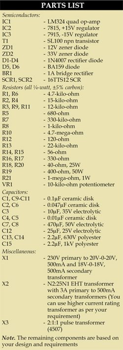
To develop a high DC voltage, ten rectifier diodes (BY255 or equivalent), each shunted by a 1-mega-ohm resistor and 0.1µF capacitor, are used in each branch of the rectifier bridge connected across the high-voltage secondary. The same is indicated in Fig. 2 by a block for simplicity. The output is further passed through the standard bleeder and filter blocks to achieve the final EHT voltage output.
Note that for suppressing the transient pulses generated due to sharp chopping of the primary sine wave, an RC network of suitable rating is required across the high secondary voltage as shown in Fig. 2.
Construction and testing
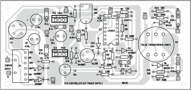
An actual-size, single-side PCB for the pulse generator circuit is shown in Fig. 3 and its component layout in Fig. 4. Assemble the circuit on the provided PCB to minimise assembly errors. The PCB for EHT generator section is not provided and all the components need to be wired separately and mounted on some insulator surface. Connect G1, K1, G2 and K2 outputs on the PCB to the assembled EHT generator section corresponding to Fig. 2. Supply the input AC power and tune VR1 as to get the required output.
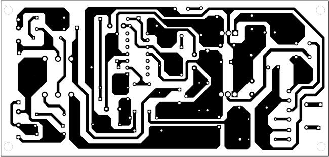
Download PCB and component layout PDFs: click here
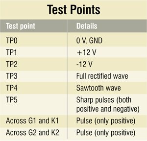
To verify the circuit for proper functioning, connect the mains input to transformer X1. Measure the regulated +12 V and -12 V at test points TP1 and TP2, respectively, with respect to TP0.
If the supply is alright, check full rectified waveform at TP3. This waveform is further converted into the sawtooth wave, which can be verified at TP4.
Also, verify the other test points (refer to the table) with respect to TP0 using an oscilloscope.
EFY notes
- Take necessary precautions when mounting the EHT Power Supply components on a proper insulator.
- EHT transformer, as well as filter chokes, need at least 10kV isolation between their windings and mounting fixtures/chassis.
The author was director CEERI Pilani in 1989. At present, he is working on developing electronics circuits for industrial applications


