This device can recognize items like vegetables and fruits and help in segregating them as well as classify them as per their size and other features. It uses the edge Impulse ML tool that can be deployed on various platforms and boards, such as Arduino, ESP32 camera, ESPEye, laptop, PC, cellphone, Raspberry Pi computer, and more. You can create the output in the form of a C++ library, which can be used almost anywhere.
Let us say you need to segregate vegetables like lemons, onions, and tomatoes, or pens and pencils. You need just a Raspberry Pi board or ESP32 camera and a few relays to segregate them. Here, we are using an ESP32 cam to identify vegetables, as an example.
Table of Contents
POC Video Tutorial In English:
POC Video Tutorial In Hindi:
When the cam detects a tomato, onion, or lemon, for instance, the relays will get actuated to open the basket containing the vegetables.
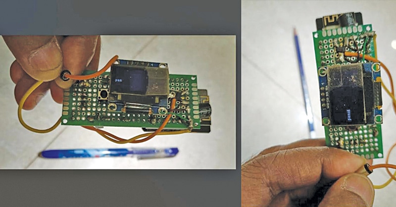
The object classification device prototype is shown in Fig. 1. The components needed for the project are mentioned in the table below.
Components Required
| Bill of Material | |
| Components | Quantity |
| ESP32 cam/ESP32 TTT GO (MOD1) | 1 |
| LM117 voltage regulator (MOD3) | 1 |
| 5V with relay | 1 |
| BC547 transistor (T1) | 1 |
| SSD1306 OLED (MOD2) | 1 |
| 100µF capacitor (C1) | 2 |
| Diode (D1) | 1 |
| FTDI USB programmer | 1 |
Setting up Edge Impulse and ESP32 Cam
ML Model Preparation
To start the project, open edgeimpulse.com and create a new project. You have to collect photographs of the items to be segregated in groups and as single pieces from several angles for the device to recognize them correctly, and edge impulse will build the project for you.
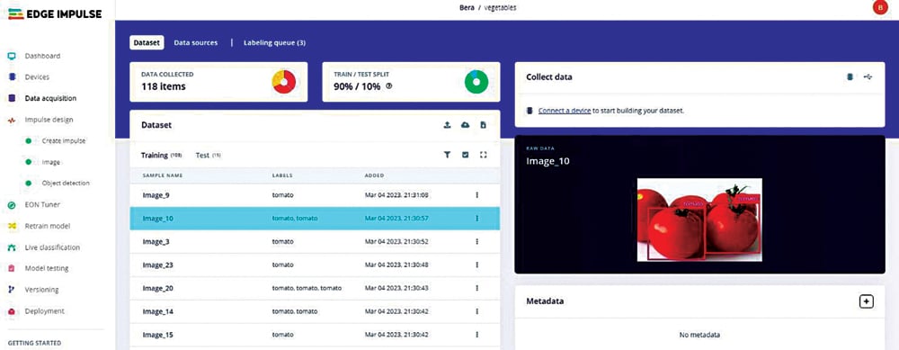
To collect pictures of the items, connect a Raspberry Pi computer and start the edge impulse project using Raspberry Pi and a phone camera or a laptop camera.
Step-by-step Guide
The following steps would make the process clear:
- Gather a substantial amount of data for the objects from various angles and combinations. Figure 3 illustrates the collection of such a dataset.
- Log in to edgeimpulse.com, create a new project, and click on “Collect data” at the top right. Then, under “Connect a device to start building your dataset” select “Data Source” and configure it to use your smartphone or laptop camera as the source for capturing the required pictures.
- Create the project by navigating to Dashboard → Devices → Data acquisition (Impulse design → create impulse → image → object detection). Once you have collected a sufficient number of pictures (e.g., 200) of all the items you wish to segregate, divide them into an 80:20 ratio for training and testing. Each image should be labeled with a surrounding box. To expedite the labeling process, utilize the “labeling queue” feature under “label suggestions” and choose “Classify using YOLOv5“.
- For simplicity, beginners can stick with the default settings in the “create impulse” and “image” sections.
- After training, check the “F1 score” which should be 85% or higher. To improve the score, you might need to adjust the model or eliminate outlier images that could negatively impact the overall accuracy.
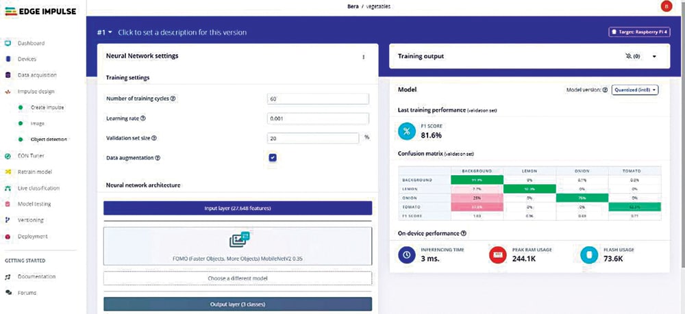
- In the “Object detection” section, choose a suitable model for classification. YOLO and FOMO are recommended models known for their ease of use and acceptable performance levels. Select the desired model and initiate the training process. Please note that this process may take some time. Figure 4 showcases the training of the ML model.
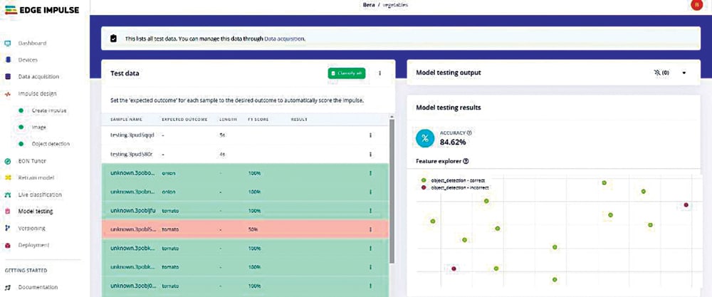
To test the model, utilize 20% of the previously set-aside data. Click on each image individually or collectively. The accuracy should fall within an acceptable range of 81% to 91%. However, achieving 100% accuracy is not ideal for the model. In such cases, intentional errors can be introduced. Figure 5 illustrates the testing of the model.
Deployment of Model
Now after testing the ML model, we can deploy it on many boards. As we are using ESP32 cam, select the Arduino IDE. Fig. 5 shows the exporting of model code for deployment.
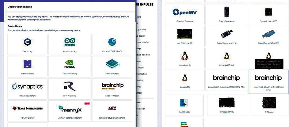
After selecting the model (Arduino), press ‘Build’ button at the bottom. The Arduino sketch, along with the necessary library, will be downloaded on your local computer. In Arduino IDE, use this zip file to install it as a new library (Sketch→Include library→Add .zip library…).
Once the library is installed, go to file→library→find the latest
library→examples→esp32_camera →your-sketch-is-here
Uploading the Sketch
The model under ESP32 is all set for the ESP-EYE camera board. The low-cost ESP32 camera available in the open market is usually the ‘ESP32 AI Thinker cam’ or a little costlier ‘ESP32 TTGO T plus camera’ model. We have set the pin details for both of these and inserted those camera models in the sketch software. You just have to uncomment the right model and the sketch is all set to get installed.
Light is required during the identification process. The ESP AI Thinker cam has a super-bright LED, which is switched on for extra light and it helps in easier detection.
The uploading process takes substantial time, sometimes 7 to 8 minutes. Therefore, have patience while uploading the sketch.
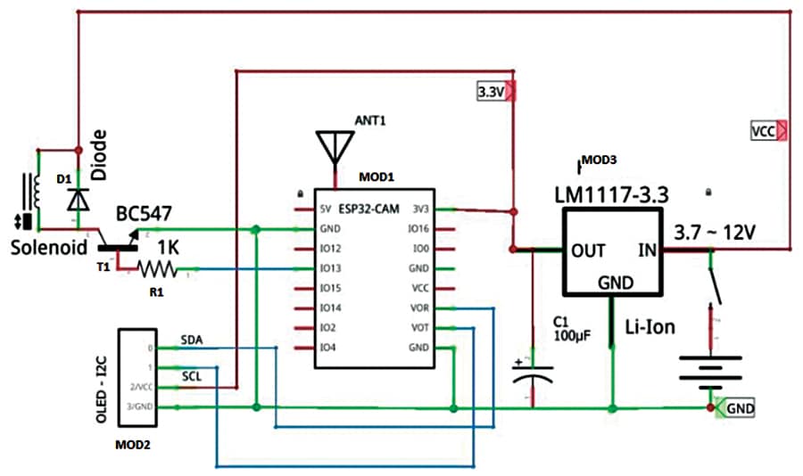
Fig. 6 shows the connections required for this vegetable detection project. It is built around ESP32 cam (MOD1), SSD1306 OLED (MOD2), LM117 voltage regulator (MOD3), and 5V solenoid with associated relays.
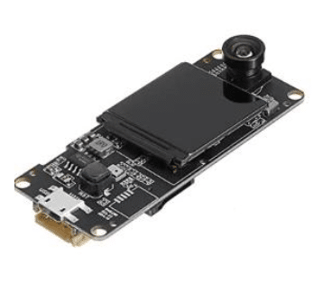
The ESP32 cam detects the articles and the output signal at its GPIO13 pin activates the solenoid. For better performance, you may use a TTGO T camera with ESP32-DOWDQ6 8MB SPRAM OV2640 camera module, which has a 3.3cm (1.3-inch) display, Wi-Fi Bluetooth board, and a Fish-eye lens, which has more RAM. Its camera pins are already defined in the sketch; just change the camera selection and it will be ready.
Circuit Diagram and Working
After uploading the source code, connect the ESP32 cam as shown in Fig. 7 for the circuit diagram, and also the author’s prototype in Fig. 1. Power the ESP32 cam and place the vegetables in front of the cam. It will display the results and move the relays to sort the vegetables.
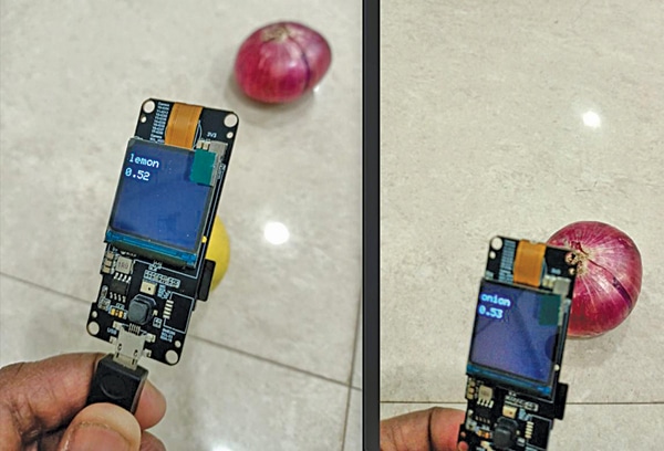
The prototype for identifying vegetables is shown in Fig. 8. This is a rudimentary project, which may need further refining to make it actually useful in a store.
EFY Note: For programming ESP32, you can use the FTDI USB programmer. Here we have described a project based for vegetable detection based on TTGO T plus camera. You can make another for pens and pencils detection based on an ESP32 camera. Both require similar connections and both project files and codes can be downloaded from electronicsforu.com.
Download Source Code
Somnath Bera is an electronics and IoT enthusiast working as General Manager at NTPC


Sir, Thank for the useful and interesting project.
In the Bill of Material LM117 voltage regulator (MOD3) mentioned while in Fig.7 Circuit Diagram LD1117 is used in MOD3. In the description also LM117 is used.
Which one should I use for MOD3? LM117 or LM1117?
Do we really need military grade regulator?