Burglar alarms have become standard equipment in stores and other businesses, and they’re becoming increasingly common in private homes as well. If you’ve ever shopped for a home security system, then you know there are a wide variety of options available. Presented here is an optical burglar alarm that you can use around your house and have fun while making it.
This optical burglar alarm uses two 555 timer ICs. Both the ICs are wired as astable multivibrators. The first astable multivibrator built around IC1 produces low frequencies, while the second astable multivibrator built around IC2 produces audio frequencies.
Optical Burglar Alarm Circuit
General purpose Darlington photo transistor 2N5777 (T1) is used as the light sensor. To increase the sensitivity of the circuit, npn transistor BC547 (T2) is used.

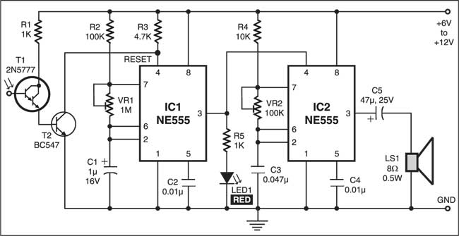
Place phototransistor T1 where light falls on it continuously. Phototransistor T1 receives light to provide base voltage to transistor T2 . As a result, transistor T2 conducts to keep reset pin 4 of IC1 at low level. This disables the first multivibrator (IC1) and hence the second multivibrator (IC2) also remains reset so the alarm (loudspeaker LS1) does not sound.
When light falling on Darlington phototransistor T1 is obstructed, transistor T2 stops conducting and reset pin 4 of IC1 goes high. This enables the first multivibrator (IC1) and hence also the second multivibrator (IC2). As a result, a beep tone is heard from speaker LS1. The beep rate can be varied by using preset VR1, while the output frequency of IC2 can be varied by using another preset VR2.
The circuit works off a simple 6V-12V DC power supply.
The article was first published in May 2004 and has recently been updated.