


 This sensitive vibration detector is realised using readily available, low cost components. One of its many applications is in a rolling shutter guard for offices and shops. The detector will sense vibration caused by activities like drilling and switch on the connected load (bulb, piezobuzzer etc.) to alert you.
Sensitive Vibration Detector Circuit
The circuit works off a 6V battery or 6V regulated power supply and uses a piezoceramic element as the vibration detector. The same is easily available from electronics/telephone component vendors or you can take it out from an active buzzer.

Circuit operation
Initially, when the power is switched on, decade counter IC1 is reset by power-on-reset components C2 and R1. As a result, Q0 output (pin 3) of IC1 goes high and the entire circuit is in idle state. LED1 indicates the power status.

In the event of vibrations, IC2 is clocked by the pulses from the piezoceramic element connected to its clock pin 14. Q1 through Q9 outputs of IC2 are fed to relay-driver switching transistor T1 through diodes D1 through D9 connected in OR mode.
Immediately after clocking, any of the outputs Q1 through Q9 would go high and npn transistor T1 would conduct. As a result, SCR1 is fired through its gate. This, in turn, energises relay RL1. The relay contacts can be used to switch any alarm device to indicate vibration detection. The circuit can be reset by momentarily pressing switch S1.

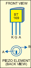
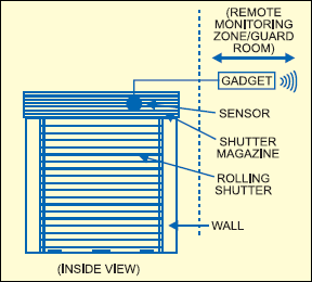
Zener diodes ZD1 and ZD2 at the clock input of IC1 are used for protection against high voltage input. In the case of repeated false triggering of IC1, add a 100nF capacitor in parallel to the piezoceramic element.The pin configuration of SCR BT169 and the back view of the piezo element are shown in Fig. 2. Fig. 3 shows suggested location other vibration detector for rolling shutters of banks, shop srolling shutters of banks, shops.
The article was first published in November 2005 and has recently been updated.
