


 This circuit lets you switch on and switch off up to nine devices sequentially from your TV remote control.
The circuit consists of an IR sensor module TSOP1738, which is equivalent to TSOP1238. The output of TSOP1738 is fed to the trigger input (pin 2) of IC NE555 (IC1) via LED1. IC1 is wired in monostable mode and its output is fed to clock input of IC CD4017 (IC2).
All the nine outputs of IC2 are connected to the bases of relay-driver transistors T1 through T9 via resistors R7 through R15, respectively. Relays RL1 through RL9 are connected between the positive terminal of 12V and collectors of respective transistors.

The circuit is powered by a 12V battery or a 12V adaptor. Since TSOP1738 needs only 5 volts (max), a 5.1V zener diode is used.
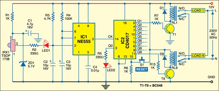

Working of the circuit is simple. At power-on, LED2 glows to indicate that the circuit is ready for operation. Now press any key on the TV remote to switch on the first device. When you press any key on the remote for the second time, the first device turns off and the second device is switched on. Further pressing of the remote key makes the devices switch on and off successively. Finally, when a key is pressed for the ninth time, the eighth device will turn off and the ninth will switch on.
Further pressing of any remote key resets IC2, which means all of its outputs, except Q0, go low. Alternatively, switch S1 can be used to reset IC2 at any time. Note that out of nine devices, only one can be switched on at a time.
Assemble the circuit on a general-purpose PCB and enclose in a suitable cabinet. Mount the sensor in the middle of the front panel of the cabinet. Complete all the relay connections on the back side of the cabinet.
