 Presented here is a project for a simple transistor’s output characteristic curve-tracer program through the serial interface and PIC microcontroller using Python programming language. Output characteristic curve of a transistor is automated using Python software and serial interface. Application software for collecting the measured value and displaying it on the monitor screen is developed using Python.
Engineers and academicians have been using high-level languages like Visual C++, Visual Basic and Delphi for connecting their gadgets/embedded systems with the computer for measurement and control purposes for a long time. Recently, many shifted their preference to Python as their computer language for measurement and analysis. The main advantage of using Python is the support of a large open source community.
Python is an interpreted programming language like BASIC, which saves considerable time during program development because compilation and linking are not required. Programs written in Python are typically much shorter as compared to ones written in C or C++.
Python can be used for writing standalone programs and scripting applications. It is free, portable, powerful and remarkably easy to use.
To run a Python program, an interpreter is required. Python interpreter is a program that reads a Python program and then executes it. To write a Python program, it is advisable to use an editor (for typing a program). An editor is designed for writing Python programs. It provides highlighting and indentation that can help you write a program without mistake.
The interpreter can be used to experiment with different features of the language. There are two modes in which interpreters can be used, namely, interactive and script. In interactive mode, the interpreter prints the result as the program is typed. The chevron, >>>, is the prompt the interpreter uses to indicate that it is ready.
Alternatively, you can store the code in a file and use the interpreter to execute the contents of the file, which is called a script. By convention, Python scripts end with .py extension. (Python installation package is available at http://python.org)
Writing the first Python Program
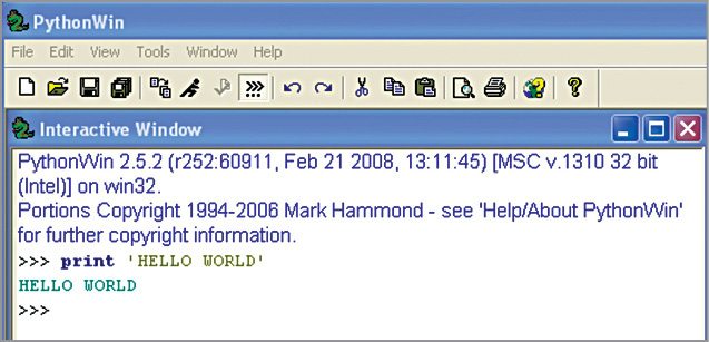
After the installation of Python IDE and PyWin32 software, you can write a program and run it. The traditional first program is Hello World. This program simply prints ‘Hello World’ on the screen when it is run. This can be done with one statement in Python, as shown in Fig. 1.
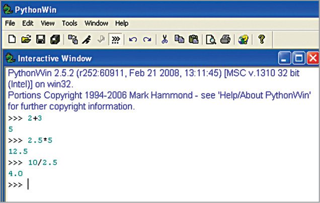
Mathematical operations are performed in a single line without declaring the variables involved, as shown in Fig. 2.
Circuit and Working
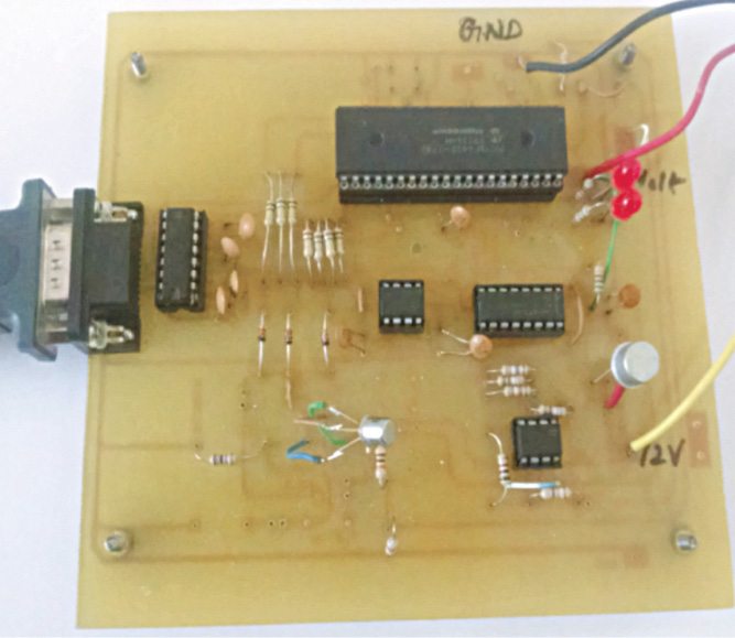
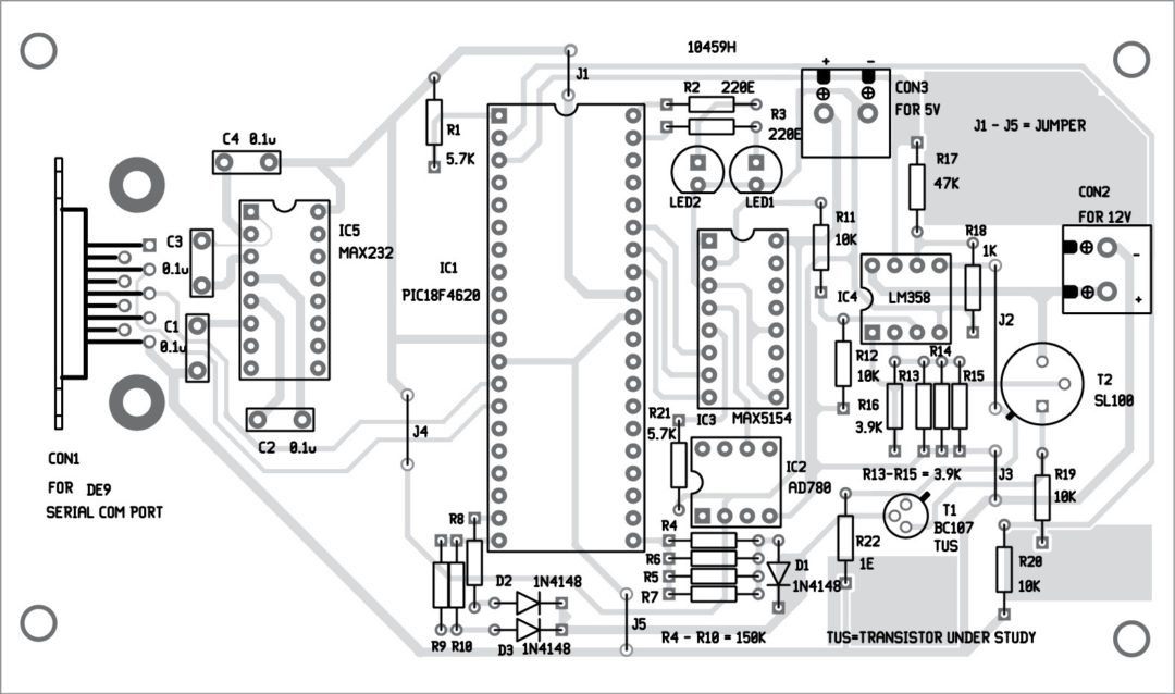
Circuit diagram of the serial interface and transistor curve tracer is shown in Fig. 3. The author’s prototype is shown in Fig. 4. The circuit consists of a PIC18F4620 microcontroller (IC1), AD780 voltage regulator (IC2), MAX5154 12-bit digital-to-analogue converter, also called DAC (IC3), LM358 voltage amplifier (IC4), MAX232 dual driver/receiver (IC5), power transistor SL100/CL100 (T2), BC107 transistor-under-study (TUS) and other essential components needed for microcontroller operations.
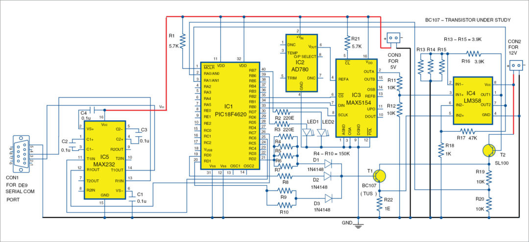
Clock frequency required for microcontroller operation is derived from its internal oscillator. Base current of TUS (T1) is varied from 0µA to 175µA in eight steps using port D pins (RD0, RD1 and RD2) of IC1. Collector voltage of T1 is varied from 0V to 2.5V in eight steps using IC1 and IC3 through IC4 and T2. Output voltage from the DAC is amplified about four times using LM358 and given to the base of T2.
Emitter of T2 is connected to the collector of TUS, whose voltage is being varied. Collector voltage of TUS is given to channel-0 (AN0) of the built-in analogue-to-digital converter (ADC) of IC1 after dividing the voltage by half using a potential divider arrangement (R19 and R20) to meet the voltage limitation of the microcontroller.
Assuming that the collector current of TUS is equal to its emitter current, output is taken across the 1-ohm resistance, and the drop across 1-ohm resistance is amplified about 50 times and given to channel-1(AN1) of the built-in ADC of IC1.
Construction
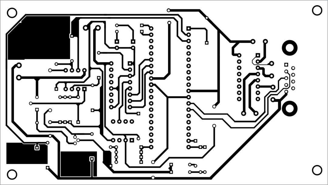
An actual-size, single-side PCB layout for the USB interface is shown in Fig. 5 and its component layout in Fig. 6. After assembling the circuit on the PCB, enclose it in a suitable box.
Firmware
The firmware is written in C and compiled using CCS C compiler. It implements the following tasks:
1. Generates different base currents
2. Generates different collector voltages
3. Measures the voltage and current (current in terms of voltage)
4. Sends the data to the PC
Host Software
The application software to collect the measured value and display it on the monitor screen has been developed using Python. It requires the following components to be installed on your system: Python 2.5 (python-2.5.2) or higher IDE, Win32 Python (pywin32-210.win32-py2.5), Serial Port (pyserial-2.2.win32), Matplot Library (matplotlib-0.91.2.win32-Py2.5) and Numeric Python (numpy-1.0.4.win32-py2.5). Output pattern is displayed using Tkinter software, and values are displayed in a text file. Tkinter software is a part of Python package, so there is no need to separately install it.
Testing Procedure
To test the project, follow the steps given below:
Step 1. Install all required software including Python2.5, Win32 Python, pyserial-2.2, matplotlib-0.91 and numpy-1.0.4 on your Windows 7 operating system.
Step 2. Power on the board (GND, 5V, 12V) and connect it to the computer through serial COM port. If physical 9-pin serial COM port is not available, use a serial-to-USB converter.
Step 3. The physical or enumerated COM port number that appears in Device Manager should be written in max5154.py script (self.fd = serial.Serial(‘//./COM18’, 115200, stopbits=1, parity=serial.PARITY_NONE))
Step 4. Place efypython and max5154 Python programs in python25 folder (under C drive), where the microcontroller is already programmed.
Step 5. Open PythonWin IDE.
Step 6. Open efypython program from pythonWin IDE. It should be in Python25 folder. Run the program using Run from Menu bar.
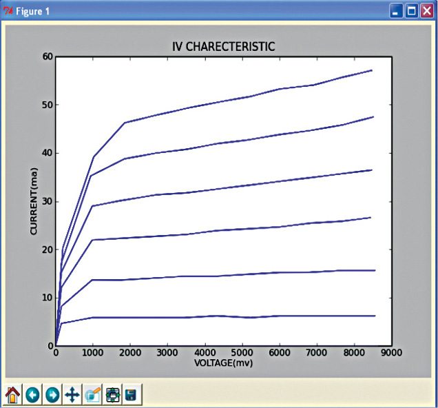
Step 7. If Python script is running, wait for a minute. The program will start showing the current and voltage values on the screen. Once measurement is over, the graph is displayed automatically. You will get the output screen as shown in Fig. 7.
The data acquisition system using Python interface can be used as a starting point for interfacing any gadget with suitable modifications. The interactive nature of Python software makes it more user friendly as compared to other visual languages.


please discuss about serial communication in python
sir why did we use the specified PIC18F462 for the project?
sir why did we use the PIC18F462 microcontroller ?can we not use any other mc in it’s place
This project was designed for PIC18F4620 microcontroller. However, you can use an equivalent PIC microcontroller. You can also use other microcontrollers for the same application but for that, the circuit, the code, and libraries will be different.