Using this shock proof remote switch circuit, you can control any AC/DC appliance remotely through inexpensive, low-voltage cabling and a standard push switch. The circuit can easily support cable length up to 25 metres. The load is triggered by a low voltage signal that helps avoid electrical shock.
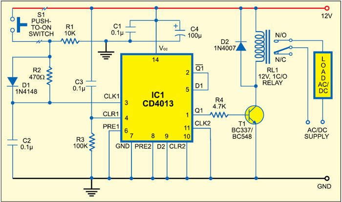
Remote switch circuit
The circuit is built around dual D-type flip-flop IC CD4013 (IC1), which contains two positive-edge-triggered D-type flip-flops. One flip-flop is wired in toggle mode, while the other is not used. The first flip-flop is clocked via its pin 3 once switch S1 is pressed. This causes its output at pin 1 to change state from low (off) to high (on), or vice versa.
Npn transistor T1 (BC548) is used to drive electromagnetic relay RL1 (12V, 1C/O). Depending on the AC/DC load voltage rating, connect the AC/DC power supply through relay contacts as shown in the figure. Resistors R1 and R2, diode D1 and capacitor C2 are used to eliminate the effect of switch-bouncing. The combination of resistor R3 and capacitor C3 provides power-‘on’ reset.

Working of the circuit is simple. Suppose you want to activate any AC load from some distance. Connect the load as indicated in the figure and provide the required power supply of 230V AC, 50Hz at the supply terminal. Extend switch S1 to the desired place through low voltage cable. When you press switch S1 momentarily, the load will turn on. On pressing switch S1 again, the load will turn off. Thus the cycle repeats.

The same circuit can be used to trigger high power loads (water pump, generator, etc) by replacing the relay by higher contact-current-rating relay.
In the circuit, push-to-on switch (S1) is used to activate/de-activate the load but the same design can be used with other triggering methods like IR, RF etc.
Construction & testing
Assemble the circuit on a general-purpose PCB and enclose in a suitable ABS cabinet. Ensure that all the mains wiring is done properly and it is completely isolated so that there is no possibility of accidental electrical contact with the low voltage side of the circuit. Push-to-on switch S1 can be connected using a two-core screened cable or something similar. Use a standard 230V AC to 12V DC adaptor for this toggle switch circuit. Alternatively, you can use a 12V battery.
This article was originally published in October 2012. It has been updated recently.
Feel interested? Check out other electronics projects.