


 Water level controllers are common nowadays. The automatic water level controller described here is built around a timer NE555 and inverter buffer CMOS IC CD4049. It uses readily-available, low-cost components, and is easy to build and install on the over-head tank (OHT) to prevent wastage of water.
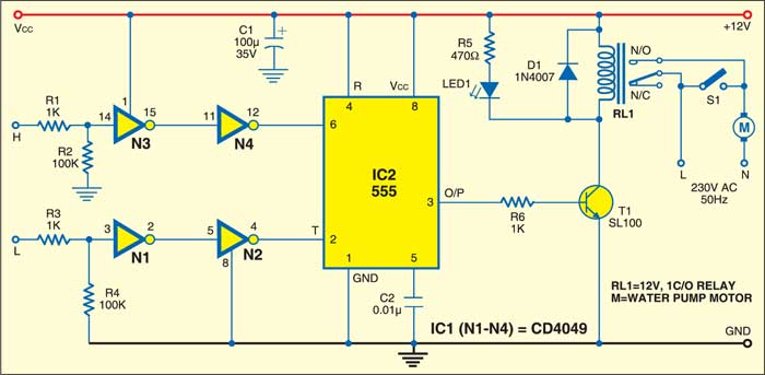
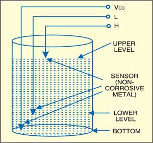
The circuit works off a 12V battery or 230V AC mains using a 12V adaptor. The three sensors built from non-corrosive metal are fitted to the OHT as shown in Fig. 2 and connected to the circuit (Fig. 1) at appropriate terminals. Power supply terminal Vcc is at the bottom of the tank, sensor terminal L is just above the bottom of the tank and sensor terminal H is at the top of the tank. After you have properly installed the sensors in the OHT and connected the power supply, the circuit is ready to use.
Since Vcc terminal is at the bottom of the tank, when the water level falls below sensor L, timer IC2 is triggered at pin 2 via inverters N1 and N2 and its output goes high. As a result, the output of timer IC2 goes high. Relay RL1 energises and the motor starts filling water in the tank. The motor remains ‘on’ even when the water level crosses sensor L.

As water in the tank rises to touch sensor H, timer IC2 is retriggered at pin 6 via inverters N3 and N4 and as a result, its output goes low. The relay de-energises and the motor stops filling water in the tank. The motor remains ‘off’ even when the water level falls below sensor H.
As water is consumed and its level falls below sensor L, the motor restarts. Thereafter, the cycle repeats.

You can also manually start and stop the motor using switch S1.
More interesting projects available here.

I have circuit this but the motor could not stop it always on
Check if transistor T1 is faulty. You can also remove it and check voltage status at output pin 3 of IC 555 as explained in the article.
Rely not stop after on the ckt ,what problem in the ckt.pls said.
Also, water is not detect.
What is the sensor name that not mentioned
Normally stainless steel rods are used as Water level sensors
PCB water contol avaible ?I want pcb it
Thanks
Kindly elaborate your query.
Does this circuit supports for submersible starter pump….
if not can you provide me upgrade of schematic diagram..
Any images for sensors…
yes we do pcb. msg me [email protected]
It would help if they include a solar panel of small size so that dependance on volatge and battery and wiring from 230v AC can be saved.
during power failure & when power comes the motor is automatically starts despite of VCC & L are well under the water & cuts off when the water level comes to H as per this circuit . that means when dc is disconnected & when reconnected the motor starts automatically despite VCC & L are well under water level. Please fix the problem as it creates repeated start of motor during repeated power cut in summer . can it be possible to switch between back up battery & transformer dc ? if yes please let us the circuit also .
what we will do after the circuit make?
I connected this circuit but not stop the motor and also can explain the relay connection..
Sir, I had build this circuit successfully,but the problem is when water is reached upto middle sensor the water pump is turned off. After water goes to down middle level sensor pump turned on..that why water tank doesn’t filled up.what can I do now???
sir how can i buy the circuit board
sir motor is not getting on when there is no water in tank
What’s the need of the not gate here?
The NOT gate 4049 IC is used here to invert the signal as well as drive 555 IC. This IC is basically an inverting buffer having high current output. It can drive TTL circuit or high capacitive loads.
As you can see in the circuit diagram, the water level sensor H comes in contact with the +12V through the water. This voltage signal may not be able to drive 555 IC directly without 4049 IC.
Sir,
I have made this circuit but when the water is touch the optimum level relayhas not stop but after all i have done.
I have done this circuit and run success fully .It works properly.
Sir, can I use multistrand wire for connect the sensor? What’s the possibile length of the sensor wire?
You can use multistrand wire and the length depends on the type of wire used. The conductivity of copper is better than aluminum, means you can use longer wire with copper as compared to aluminum wire.
When power stops and resumes, the motor is starting irrespective of the level of water in the tank. Is there any solution to this issue?
Sir, I built the circuit on pcb and I got the output. But after sometime it didn’t work. It produce noise when water comes to H level and it doesn’t cut the relay properly. Relay goes to on and off with tik tik sound. How can I solve this problem?
First, check the correct power supply and correct voltage rating of the relay.
Second, make sure you have diode 1N4007 connected across the relay.
Third, check any loose connections in the transistor
LAST ONE YEAR THIS CIRCUIT WORKING ..PERFECTLY
Thank you for your feedback.