


 This article describes a simple, low-cost DC to DC converter for a microcontroller (MCU) kit. This converter is built around popular NE555 timer. It can provide positive and negative output voltages simultaneously. Output currents are limited only by the output capabilities of NE555.
Most MCU kits on the market are available with a single power supply, mostly +5V DC. Also, the transformer with or without a rectifier is usually external, for example, in the form of a wall adaptor. But for many experiments and real-world projects, we need power supplies that provide a bit higher voltages than +5V and a bit lower than the ground such as +7.5V and -2V, respectively.
You may use an external power supply for providing these voltages. But since the required currents are usually a few milliamps, you can use a low-power DC to DC converter to produce the needed voltages. Power supply for the DC to DC converter can come before or after the regulator for +5V. But the produced output voltages (+Vout and –Vout) will depend on input voltage.

Circuit and working
Fig. 1 shows the circuit diagram of the DC to DC converter (MCU kit companion board) built around NE555 (IC1). The board is also called DC-DC companion board because it is complementary to the MCU kit for many applications. NE555 works as a square-wave oscillator.
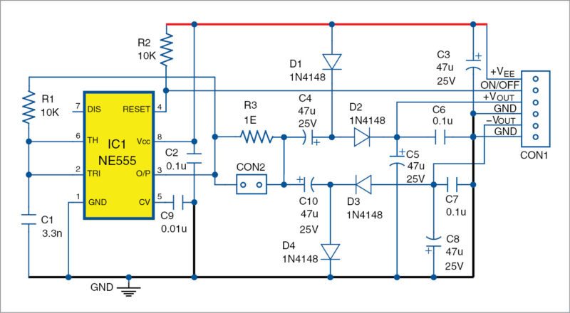
Frequencies depend mainly on resistor R1 and capacitor C1, and can be selected up to around 200kHz. With R1 as 10-kilo-ohm and C1 as 10nF (0.01µF), 5.1nF, 3.3nF and 330pF, we have frequencies around 7kHz, 14kHz, 20kHz and 150kHz.

Capacitors C4, C5 and C6, and diodes D1 and D2 produce positive output voltage (+Vout). With a 9V input power supply (+VEE = +9V) the circuit produces +VOUT around +16V without any load, +14.5V with 15mA load and +13V with load of 20mA. This is enough for giving power to several operational amplifiers and comparators that have low power consumption.
Diodes D3 and D4, and capacitors C7, C8 and C10 produce the negative output voltage (-Vout). With +VEE = 9V power supply, the circuit produces -VOUT around -7V without any load, -5.3V with load of 16mA and -3.7V with load of 35mA. This is good enough for many analogue and interface applications.
Resistor R3 and connector CON2 (in Fig. 1) are important to check output current of the timer at CON2. This current should always be below the maximum, which is 200mA for NE555.
Fig. 2 shows how to connect the DC to DC converter to a wall adaptor, MCU kit and input/output (I/O) expansion board.
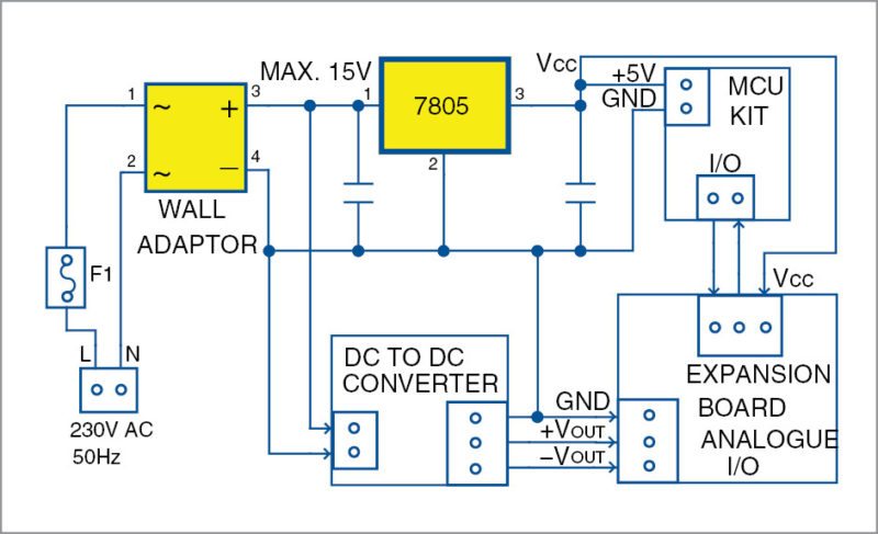
Fig. 3 shows how to connect popular operational amplifiers to the DC to DC converter board. Output voltages of the converter depend on the load. That is not a problem in many cases and, if you want, you can restrict and regulate these to particular predefined levels.
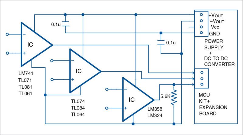
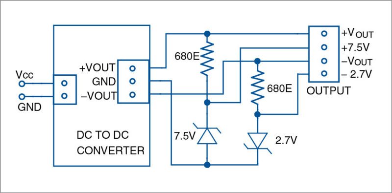
Fig. 4 shows how to regulate output voltages of the DC to DC converter with low-cost Zener diodes like 1N4737 (7.5V), BZX85C2V7 (2.7V), BZX55C2V4 (2.4V) and so on. This circuit shows two different Zener diodes to get regulated voltages such as +7.5V and -2.7V.
Construction and testing
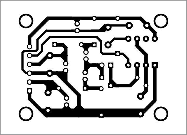
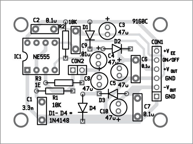
A PCB for the DC to DC converter circuit (Fig. 1) is shown in Fig. 5 and its component layout in Fig. 6. Enclose the PCB in a suitable box and provide connectors for 230V AC adaptor for input and CON1 for output.
Download PCB and component layout PDFs: click here
It is preferable to select the working frequency above 20kHz. (During testing we have used around 7kHz frequency. But that depends on the requirements for the power supply of the embedded system and parameters of the components in the converter.) The circuit does not need any adjustment and will start working immediately after proper connections are done.
It is recommended to use fast-switching, low-voltage-drop diodes. 1N4148 would work but 1N5819 or similar is preferred. 1N400X series diodes are too slow for most applications but will work at low switching frequencies. Capacitors should be used for high-frequency switching power supplies.
Note
PCB layout for the circuit in Fig. 1 only is shown here. Remaining circuits (Figs 2, 3 and 4) can be wired on general-purpose PCBs.
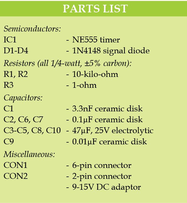
Parts list is also of the circuit shown in Fig. 1 only.
Petre Tzv Petrov was a researcher and assistant professor in Technical University of Sofia (Bulgaria) and expert-lecturer in OFPPT(Casablance), Kingdom of Morocco. Currently, he is working as an electronics engineer in the private sector in Bulgaria.
