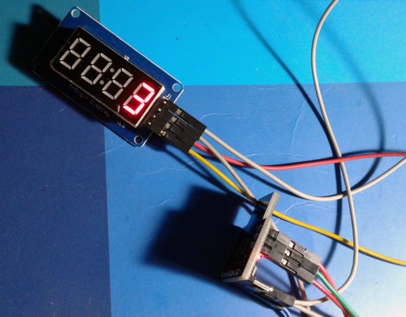
Microcontroller based miniscule event counter presented here is based on the inexpensive Digispark Attiny development board. One advantage of this design is that any type of active or passive switch can be connected to its trigger input. Whenever the switch closes event will be counted inside the microcontroller and would be displayed on the 4-digit LED display module, a type generally known as TM1637 LED Display. The circuit can be driven from any 9V dc source capable of catering atleast 500mA of current to the connected device. Virtually there is no limit to what you can do with this digital event counter!
Event counter hardware overview

Microcontroller
The Digispark Attiny85 is a handy microcontroller for simple projects. Both the genuine versions, and the clones come with pre-installed micronucleus bootloader. The micronucleus bootloader allows us to program the ATTINY85 with a USB connection. This is well documented on the digistump site (https://digistump.com/wiki/start).
Digital Display
As stated, core of the display module is TM1637, a special kind of LED driver/controller chip from Titan Micro Electronics (www.titanmec.com). TM1637 requires only a two–wire bus interface (CLK & DIO) for communication with any microcontroller. However, note that this communication method is not similar to the famed 12C bus protocol because there is no slave address, and for the right data transfer, an answering signal (ACK) is generated inside the chip.
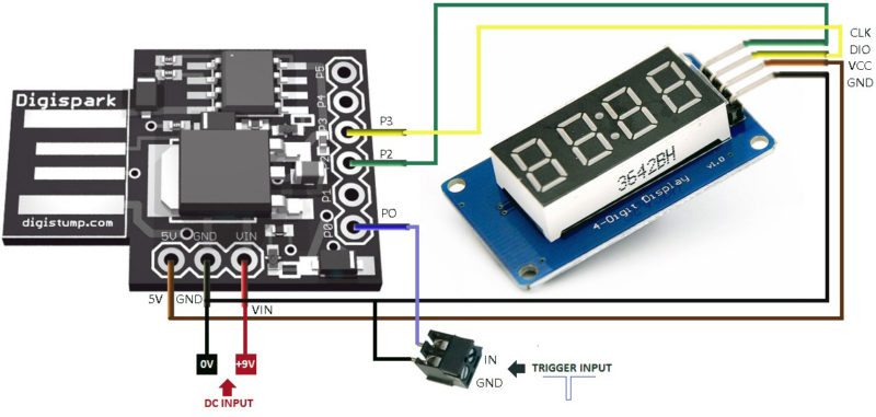
In addition to these two essential parts, only a few discrete components are required to complete the hardware setup. See the schematic diagram of the event counter shown below.
Software Inside
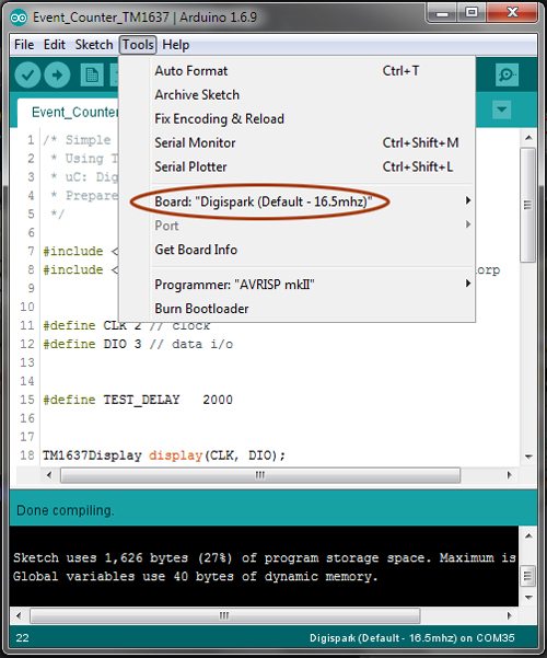
Like the hardware, software is also very simple with only a few lines of code. A special library “TM1637Display” is included as it is crucial here. Well-commented code shown below can be handled through Arduino IDE (1.6.9). Just copy-paste-compile-upload; that’s all. Note that the TM1637Display library can be installed as any other Arduino library, by copying the files into a directory on the library search path of the Arduino IDE.

[stextbox id=”grey”]
/* Simple Event Counter
* Using TM1637 LED Display
* uC: Digispark Attiny85
* Prepared by T.K.Hareendran
*/
#include
#include //essential library from avishorp
#define CLK 2 // clock
#define DIO 3 // data i/o
#define TEST_DELAY 2000
TM1637Display display(CLK, DIO); //setup the display
void setup()
{
pinMode(0,INPUT); // counter trigger input pin
digitalWrite(0,HIGH); // enable internal pull-up
display.setBrightness(6); // brightness level 0-minimum, 7-maximum
}
int numb=0;
int pres=0;
void loop()
{
display.setBrightness(0x0f);
display.showNumberDec(numb,false); // function to display numbers upto 9999
if(digitalRead(0)==0) // read counter trigger pin
{
if(pres==0)
{
numb++;
pres=1;
}
}
else
{
pres=0;
}
}
[/stextbox]
Pre-Flight Test
After the build up, connect a normally-open (N/O) push button switch to the trigger input socket, power up the circuit, and wait for five seconds. After the initial delay, you can see digit zero (0) at the rightmost of the LED display. Now press the push button switch, and ensure that the counter increments with each one button input. If you’ve made it to this point, it’s sure that your event counter is in functional order. Start counting, enjoy!
Enhancement
As you observed, almost all normally-opened mechanical switches (like tactile switch, reed switch,etc) can be connected to the trigger input of this event counter without any circuit modification. Active switches (a hall sensor, for example) with open-collector outputs can also be connected in this way. No additional resistors are necessary here because the trigger input (P0 of digispark) is pulled-up by an internal resistor of about 25K value (see the code). However, if you want to trigger the event counter from any active switch/sensor with a logic-high level output, an add-on circuit is required. Here is a cheap’n’cheerful solution to accept active-high (H) signals from the external world.
Download Source Folder
Check out the working of this project here.


