


 A radio or FM receiver is an electronic device that receives radio waves and converts the information carried by them to a usable form. An antenna is used to catch the desired frequency waves.
The receiver uses electronic filters to separate the desired signal from all the other signals picked up by the antenna, an electronic amplifier to increase the power of the signal for further processing, and finally recovers the desired information through demodulation.
Of the radio waves, FM is the most popular one. Frequency modulation is widely used for FM radio broadcasting. It is also used in telemetry, radar, seismic prospecting, and monitoring newborns for seizures via EEG, two-way radio communication systems, music synthesis, magnetic tape-recording systems, and some video-transmission systems.
An advantage of frequency modulation is that it has a larger signal-to-noise ratio and therefore rejects radio frequency interference better than an equal power amplitude modulation (AM) signal.
We have also designed a simple stereo amplifier circuit.
A radio or FM receiver is an electronic device that receives radio waves and converts the information carried by them to a usable form. An antenna is used to catch the desired frequency waves.
The receiver uses electronic filters to separate the desired signal from all the other signals picked up by the antenna, an electronic amplifier to increase the power of the signal for further processing, and finally recovers the desired information through demodulation.
Of the radio waves, FM is the most popular one. Frequency modulation is widely used for FM radio broadcasting. It is also used in telemetry, radar, seismic prospecting, and monitoring newborns for seizures via EEG, two-way radio communication systems, music synthesis, magnetic tape-recording systems, and some video-transmission systems.
An advantage of frequency modulation is that it has a larger signal-to-noise ratio and therefore rejects radio frequency interference better than an equal power amplitude modulation (AM) signal.
We have also designed a simple stereo amplifier circuit.
FM Frequency Ranges
Frequency modulation is used in a radio broadcast in the 88-108MHz VHF frequency band. This bandwidth range is marked as FM on the band scales of radio receivers, and the devices that are able to receive such signals are called FM receivers. The FM radio transmitter has a 200kHz wide channel. The maximum audio frequency transmitted in FM is 15 kHz as compared to 4.5 kHz in AM. This allows a much larger range of frequencies to be transferred in FM and thus the quality of FM transmission is significantly higher than that of AM transmission. Presented below is an FM Radio Circuit Diagram along with its full explanation.FM Receiver Circuit – Components
- IC- LM386
- T1 BF494
- T2 BF495
- 4 turn 22SWG 4mm dia air core
- C1 220nF
- C2 2.2nF
- C 100nF * 2
- C4 10uF
- C5 10uF (25 V)
- C7 47nF
- C8 220 uF(25 V)
- C9 100 uF (25 V) * 2
- R 10KΩ * 2
- R3 1KΩ
- R4 10Ω
- Variable resistance
- Variable capacitance
- Speaker
- Switch
- Antenna
- Battery
FM Receiver Circuit Explanation
Here’s a simple FM receiver circuit with minimum components for local FM reception. Transistor BF495 (T2), together with a 10k resistor (R1), coil L, 22pF variable capacitor (VC), and internal capacitances of transistor BF494 (T1), comprises the Colpitts oscillator. Trimmer VC sets the resonance frequency of this oscillator to the frequency of the transmitting station that we wish to listen to. That is, it has to be tuned between 88 and 108 MHz. The information signal used in the transmitter to perform the modulation is extracted on resistor R1 and fed to the audio amplifier over a 220nF coupling capacitor (C1).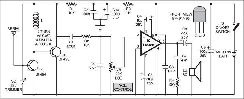
Antenna is a Bit Tricky…
You can use the telescopic antenna of any unused device. However, A good reception can also be obtained with a piece of isolated copper wire about 60 cm long. The optimum length of copper wire can be found experimentally. You can also Read: Different Types of Antennas The performance of this tiny receiver depends on several factors such as quality and turns of coil L, aerial type, and distance from the FM transmitter. IC LM386 is an audio power amplifier designed for use in low-voltage consumer applications. It provides 1 to 2 watts, which is enough to drive any small-size speaker. The 22k volume control (VR) is a logarithmic potentiometer that is connected to pin 3 and the amplified output is obtained at pin 5 of IC LM386. The receiver can be operated off a 6V-9V battery.This circuit costs around ₹120.
More on FM receivers in the slideshow below.
Chapter 5: FM Receivers from mkazree
Related FM Transmitter Projects:
This article was published in June 2003 and recently updated on August 2023.
- Advertisement -

which kind of antenna is useful here, in this receiver?
You can use simple single strand copper wire or whip antenna for testing.
HEy !! Have u published any video of working of this project anywhere?
use Telescopic Antenna if you are near to the radio station . If u r in a remote area use dipole with booster .
i have a transistor radio but dont know how to convert to a small transmitter! help me please
Your transistor radio is receiver and may not possible to work as transmitter
if i use a mp3 song from my smartphone as my message signal to the transmitter and if transmit it , can i use this circuit to reciever , like can i tune this circuit to the transmitter frequency
Yes, you can receive the signal in this circuit provided you tune it to the same frequency
is that a digital fm receiver?
No, its analogue FM receiver
may i see a photo of antenna
You may refer to photo of commonly available aerial or whip antenna from here : http://www.ccrane.com/CCRadio-CCRadioPlus-Replacement-Whip-Antenna
Your diagram and apparatus list are not same.
We have checked the list and compared it to the diagram. Please let us know the what are the components that are not same.
I tried so many times. It doesn’t work. Please, I need your help @EFY’s
Kindly elaborate your query.
Please note that if you are near a commercial FM broadcast station, you can receive the FM channel signals in this circuit. Otherwise, you won’t receive the commercial broadcast signal. This is because it is a simple circuit and does not have the power and sensitivity to receive the weak signal.
However, you can construct any FM transmitter circuit which works in the FM band 88-108 MHz and
receive the transmitted signal using this simple FM receiver circuit.
I agree – this circuit does not work. The RC Low Pass filter to the 22k pot is doing its job (sort of). The cut-off needs to be sharper (around 7kHz at -3dB). There is also no envelope detection FM to AM conversion so not sure how audio is achieved at the speaker. See slides at bottom of this article for FM detection.
i want to buy this ckt..
You may want to add a voltage regulator to the circuit if you want tuning stability when running from a battery.
What should I use as ground in this circuit? C3 and C10 are supposed to go to ground, but I am running off a battery here?
I just looked up the data sheet for the BF494 at Philips, and noted that the Collector and Base in your diagram seem swapped. Are you aware of that?
no it is the same as the schematic above.
What should I use as ground in this circuit? C3 and C10 are supposed to go to ground, but I am running off a battery here?
Would it still be fine to use an air variable capacitor instead of a trimmer, or are there any major disadvantages?
You can use any 22p variable capacitor in place of trimmer.
Does the coil have to turn left, as indicated as L, or is that just labelling?
This ‘L’ is just the symbol of inductance for the inductor used in the circuit.
what is the pcb layout??
PCB layout is not available for this circuit.
Any equivalent transistors for BF494….?
You can use BF495 in place of BF494. They are easily available from various vendors.
Thanks for the circuit, i’ll build it as fm prototype for training to students.
It is rather difficult to find tr Bf495. Is there the substitu for this.
Waiting for your answer. Thanks.
Any equivalents for BF494 & BF495 transistors……?
can we use function generator of oscilloscope as an input.
sir i have made this project and unable to listen radio .. i have used trimmer (green color ) 22swg 0.26 inch diameter 7 turn , can i used 22swg to thinner copper wire ??
Sir can I use 2N2222A tansistor instead of bf494?
Could you give me the voltage levels obtained at different terminals in this particular circuit. @efylab
This is very easy and Sensitive circuit. But when i tested it did not work. this circuit is able searchable Radio Frequency but no Get any Signal of any Station. What may be problem ?? When i remove the 10K resistor after 220n capacitor and connect direct the output then i get even noise output. But with 10K resistor nothing get any output.
Reception of weak signals can be improved by connecting an outdoor yagi antenna in the case of TVs. But for FM radios, simply connecting a long outdoor wire to the telescopic antenna does not improve; on the other hand worsens, perhaps due to shift of resonance frequency or something. There is no radio having coaxial antenna socket. Can it be possible to fix a coaxial outdoor antenna input socket to a simple FM radio for inserting an antenna balun to make reception as good as TVs ? Pl suggest any other means to improve reception.
how is the circuit demodulating the frequency modulated wave?
can u post the explanation?
@efylab
Can you please tell how and where in the circuit is demodulation done?
What variable resistor and variable capacitor should I use for this project?
What is the inductance of the coil?
I have tried to build the project but it didn’t work out, and it doesn’t compare with the datasheet of the LM 386.
Why is the Vs via C6 going to the ground?
where is demodulation and amplification taking place on the circuit please explain ASAP
Comment:how do i simulate to see the carrier frewuency and the message sugnals with the oscilloscope
Hi, would like to construct 144-146 MHz receiver, please suggest if this can be modified.
Congrats, so successful!
The circuit doesn’t work.. Waste of time
Kindly elaborate your query.
Hi Jacob! Thanks for the feedback! Can you please tell us the problem in detail. Problem could be very simple to silly to major one. You can also contact EFY Lab team directly at [email protected] for technical problems.
There is only a humming sound whats the problem??
What frequency demodulation method does this circuit follow?
Are you providing PCB with the FM radio kit.?
Why is that AM Radio Circuit lost signal if one component is remove ? unlike for the FM(LF) Radio Circuit it does not?
My experience is circuit ideas published by Efy are never successful. To construct the circuit & make a project is wasting of time. Efy has spoiled career of many electronic engineers & technicians
Umm, how do we actually DETECT the frequency variation? Definitely a problem. Better to use an FM receiver on a chip and build from there.
Have you tested this circuit? Did it work?
doesnt work, waste of time
Could you please elaborate on this?
Correct me if I am wrong… The frequency range of BF494-495 is somewhere at 200MHz. The transistors could be replaced provided that the input frequency will not somewhat exceed the frequency range the consequences is rather a mumble output. The BC547 which was used also in the transmitter circuit was used to replace BF494 and 495.
im transmitting from my phone with a FM transmitter, i get some sparkling sound on certain frequency to you know what might be the problem ?
I want laser radio .can I built it
sir, are you in toronto. can i have your mobile and email as i need to have your help personally to fix my fm receiver.
You can email your query at [email protected]
How about one with tubes? Yes long gone but they are still around and work! The one with the ECC85 and other tubes. How do you play with the range it works without experiments, how do you tune it etc. it is much more didactic to try than with transistors only, inspite of the HV. Tks.
The circuit was designed and tested with transistor only. Tubes are not easily available in the market.
Tuning is done using trimmer(VC) and volume control with 22k potentiometer as given in the circuit.
I’ve completed this project on a protoboard and it doesn’t seem to work. Connections have been thoroughly checked in comparison to the schematic above. Everything was done as shown on the schematic with the exception of the transistors and inductor. For both transistors, the 2N3707 was used which is equivalent to the BF494. The 2N3707 was used in place of the BF495 because in a previous question you stated a BF494 will work in place of a BF495. The inductor is a 24AWG Enameled copper wire consisting of 12 loops, each being 4mm in diameter. Even after adjusting the potentiometer and variable capacitor in various positions, no sound is emitted from the eight-ohm speaker.
Also, I noticed quite a few questions unanswered on this thread that could potentially provide people with solutions;
SB’s Question
“I have tried to build the project but it didn’t work out, and it doesn’t compare with the datasheet of the LM 386. Why is the Vs via C6 going to the ground?”
Arne’s Question
“I just looked up the data sheet for the BF494 at Philips, and noted that the Collector and Base in your diagram seem swapped. Are you aware of that?”
Not sure whether this is a problem on my side or yours, but a lot of people seem to be complaining about the radio not working. I’m sure you got your’s working so there may likely be a translation error between your actual project and the information posted on this page. Maybe we can exchange images of our finished projects and figure out what the problem is. Just like anyone else, it makes me angry to put money and time into something that should work, but doesn’t. Thanks in advance.
how to calculate amplification factor for this pls explain it
This circuit not works. I tried many times with same circuit connection. No signal catches.
I think This is Fake circuit
Built this and does not work, the LM368 amp works fine, but the tuning coil with capacitor do not pick up RF.
Something is wrong here, i built it on a perf board with short soldering distances and it does not pick up anything, even a programmable Arduino transmitter is not picked up while my boafeng pick up the transmitter without any issues.
Can someone please answer the question that has been posed many times, and help all of us that are eager to learn and understand? Where is the signal extraction occurring? Is the incoming RF affecting the base/collector capacitance thus affecting the frequency of the oscillator, then relying on slope detection (frequency response of the LC circuit in the collector leg), or, is this circuit relying on the nonlinearity of the base/emitter junction causing the mixing (multiplying) of the incoming RF and the oscillator signals and causing an intermediate frequency?
This would work better as an AM receiver. There is no FM detection circuit. Needs an RF choke at the battery +ve terminal. The bandpass filter is not required. These are just smoothing capacitors (C3, C6, C9, C10) to take the ripple off Vs (pin 6) of LM386. AGAIN – there is no FM detection or FM-AM conversion, so don’t see how this will produce audio. During testing, I fed FM (100MHz) signal directly from AWG with 1KHz mod frequency 2khz freq deviation. Could see the attenuated carrier and the modulated frequency at PIN 3 of LM386. Output did show modulated frequency but still with freq deviation rather than amplitude modulation.
Can I transmit signals from an FM walkie-talkie to this receiver?
Yes, you can transmit signal from any FM device operating within FM band (88-108MHz) and then receive it from this FM receiver.
Note the Pinout arrangement BF494, generally the Centre pin is the Base where as in this case it is the Emitter in a TO-92 package. I am guessing probably this could be one reason for the failure
checkout the Base & emitter & collector pinout of the BF494 TO92 package .The centre pin is the emitter in present case which i am guessing probably explains many of the failures.
Totally agree. Pin outs of BF494 is different from the commonly available TO-92 package transistors. The middle pin is emitter. User should check manufacturer’s datasheet before using the component.
yur missing a signal diode or FM discriminator.
what is the value of modulated frequency?
Sir, how can I increase the bandwidth to 76-108 MHz? How can I extract RDS text?