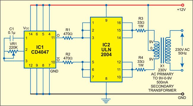
 Here is a simple low power inverter that converts 12V DC into 230-250V AC (DC to AC Converter).
It can be used to power very light loads like window chargers and night lamps or simply give a shock to keep the intruders away.
The circuit is built around just two ICs, namely, IC CD4047 and IC ULN2004.
Circuit and Components
- IC CD4047: IC CD4047 (IC1) is a monostable/astable multivibrator. It is wired in astable mode and produces symmetrical pulses of 50 to 400 Hz, which are given to IC2 via resistors R1 and R2.
- IC ULN2004: IC ULN2004 (IC2) is a popular 7-channel Darlington array IC. Here, the three Darlington stages are paralleled to amplify the frequencies received from IC1. The output of IC2 is fed to transformer X1 via resistors R3 and R4.
- Transformer X1: Transformer X1 (9V-0-9V, 500mA secondary) is an ordinary step-down transformer that is used here for the reverse function, i.e., step up. That means it produces a high voltage. Resistors R3 and R4 are used to limit the output current from the ULN to safe values. The 230-250V AC output is available across the high-impedance winding of the transformer’s primary windings.

Enhancements for an Optimized Low-Power Inverter Design
- Battery Monitoring Circuit: Include a low-voltage cutoff circuit to protect the battery from deep discharge, hence increasing the inverter’s longevity.
- Overload Protection: Consider installing a fuse or circuit breaker to avoid damage in the event of an overload, resulting in safer operation.
- Adjustable Frequency Control: Using a potentiometer, you can change the frequency range and adjust the inverter for different purposes.
- Cooling Mechanism: If the inverter will be operating continually, attach a tiny heatsink to IC2 to prevent overheating.
- Efficient Power Output: To improve efficiency, replace the transformer with a toroidal transformer, particularly if the inverter will be used frequently.
- Expand Power Capacity: Consider parallel setups or a higher-rated transformer if you intend to operate somewhat heavier loads.
Related Projects:
The article was first published on 5 December 2017 and has recently been updated in November 2024.


Tell the value of C1 capacitor
adjust c1/vr1 to give you the frequency you like.
Can you incorporate it with MOSFETs?
this can be work
Please tell in which software we can simulate this..
You can simulate it in Proteus
hello I want to make my own handmade inverter I want to make your own help pcb card with the names of the places where the electronic malz will be soldered and the holes of the places where the material will be soldered are also written It’s going to be the biggest help you can do to me, but this inverter technical oscillar should be 12 volts dc output 220 volts 5000 watts for the battery short circuit in the output Protection overcurrent protection Should have replacement lights to alert me to any failure I need to be able to install indicators that show the battery volatility and the current used to show the tiny voltage I’d appreciate it if you’d help me with that. also contact to whatsup phone number +90 531 518 1929