


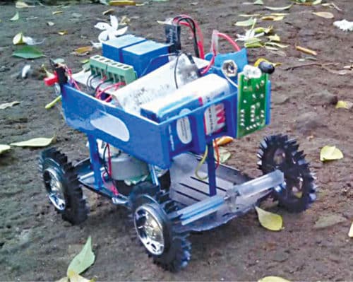
 Presented here is an obstacle-avoidance robot without microcontroller (MCU). The obstacle-avoidance feature is commonly found in autonomous cars and robots. Most obstacle-avoidance robots are costly and difficult to build because of MCUs. This project is simple and does not use any complex circuitry except a relay driver. The author’s prototype is shown in Fig. 1.
Circuit and working
The circuit diagram of the simple obstacle-avoidance robot is shown in Fig. 2.
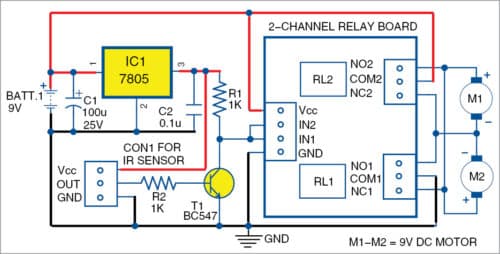
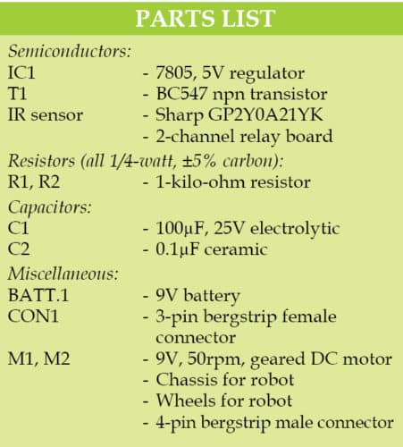
The circuit consists of 2-channel relay board, IR sensor, transistor BC547 (T1), 7805 5V regulator (IC1) and a few other components.

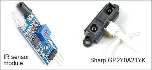
Commonly-available IR sensor modules are shown in Fig. 3. GP2Y0A21YK IR sensor was used during testing. However, any equivalent IR sensor module easily available in the market can be used. The author used a different type of IR sensor in the prototype.
The circuit uses a 9V battery to drive the robot. 7805 (IC1) is used to convert 9V to 5V regulated output to drive the sensor module. IR sensor output is amplified by T1. The final IR sensor signal is taken from the collector of T1 and fed to inputs IN1 and IN2 of the relay board.

IR sensor is mounted in the front of the robot. When the sensor detects an object or obstacle, it moves away from it—instead of moving towards the obstacle or colliding with it.
To make the robot change directions when it detects an obstacle, make one wheel rotate and the other wheel either stop or rotate in opposite direction. To achieve that, connect the motors to the 2-channel relay board as shown in Fig. 2. Connections are done through normally-open (NO) and normally-closed (NC) contacts of relays RL1 and RL2. Any suitable 2-channel relay board can be used.
Construction and testing
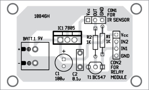
An actual-size PCB layout for the obstacle-avoidance robot is shown in Fig. 4 and its components layout in Fig. 5.
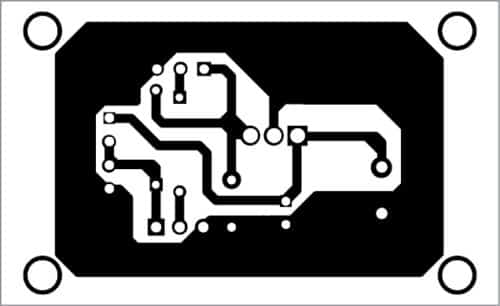
Download PCB and Component Layout PDFs: Click Here
After assembling the circuit on the PCB, mount the PCB on the chassis along with 9V battery. Connect two 9V, 50rpm to 100rpm geared DC motors across M1 and M2 for rear wheels. For front wheel(s), either use a castor wheel or two suitable wheels without motor.
After connecting 9V to the circuit, the robot will move forwards (straight) until it detects an obstacle. Depending on the way the motors are connected to relay contacts, one of the motors will continue to move, while the other will either stop or move backwards to prevent colliding with the obstacle.
Ashwini Kumar Sinha is an electronics hobbyist

The robot is moving in forward and backward directions only. How to take turn?
Connect one motor Directly to battery and other through relay