 Here is a simple stereo amplifier you can make with a CD6283 audio amplifier and a few passive components. It provides an output of 4.6 watts per channel with a 12V power supply.
Circuit diagram of the stereo amplifier is shown in Fig. 1. CON1 is the connector for 6-12V input power supply, CON2 is for the input signal and CON3 provides the output to two speakers that may be connected to it.
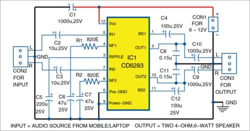
Pins 5 and 7 of IC1 are connected to CON2 for audio inputs via capacitors C2 and C3, respectively. Pin 12 is connected to CON1 connector for power supply. Pin 2 of IC1 is connected to left (L) channel output via electrolytic capacitor C10 and pin 10 of IC1 is connected to right (R) channel output via electrolytic capacitor C9. A 4-ohm, 4-watt speaker each is connected at CON3 for left and right channels, respectively.
Construction and testing
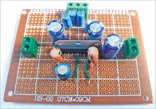
A PCB layout for the amplifier is shown in Fig. 2 and its components layout in Fig. 3. After assembling the circuit on the PCB, connect a 6-12V power supply across CON1.
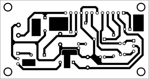
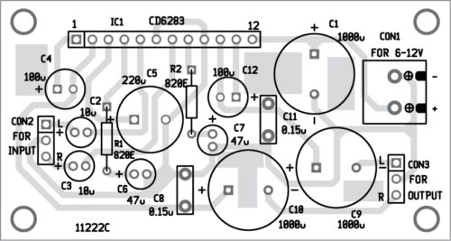
After completing the wiring, connect left (L) and right (R) stereo audio inputs from a mobile/laptop/desktop at CON2. Then connect the speakers at CON3. Take a 6V or 12V battery and connect it to the amplifier circuit.
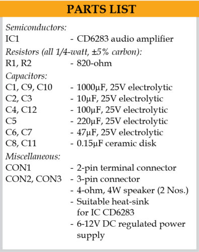
You can calibrate the circuit by connecting a signal generator (set at 1 kHz) to left and right inputs at CON2. You should hear a loud amplified tone from left and right speakers at the output. You can also use an MP3 player instead of signal generator to calibrate the circuit.
Optional 22-kilo-ohm potentiometers can be connected at CON2’s left and right inputs for volume control. Your amplifier is ready to use!
Raj K. Gorkhali is a hobbyist and a regular contributor to EFY


Sir pcb size kya Hai please tell me sir
The designed PCB size is around 7cm x 4cm. You can also use veroboard or zero PCB with the same size to assemble this circuit.
Dear Sirs,
is there a download link for the PCB and Components Layout?
Kind Regards
Mitsos
Hi, You can download it via saving the image from the article.