


 Usually, low-priced home stereo power amplifiers don’t have output level indicators. An output power level indicator can be added to each channel of these stereo power amplifiers. As low levels of the output power are not disturbing and damaging to the people, there is no need to add a preamplifier and low-level detector before IC LM3915. But you should know when the output power becomes considerably high.
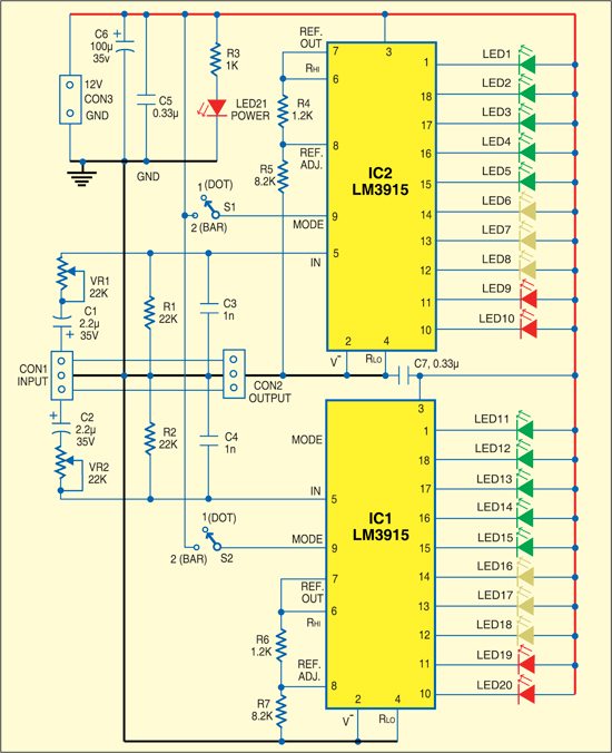
Here we present a very simple, low-cost stereo-level indicator circuit for home power amplifiers with power rating of around 0.5W. The circuit is built around two LM3915 dot/bar display driver ICs (IC1 and IC2). LM3915 senses analogue voltage levels to drive ten LEDs, providing a logarithmic 3dB/step analogue display.

The voltage levels below 1V are not important because these correspond to a low level of the audio signal. Similarly, input voltage levels above 30V correspond to too high levels of the output power, which are not applicable for home power amplifiers. So the voltage levels of our interest are 1V to 30V, which can be handled directly with LM3915. LM3915 needs no protection against ±35V inputs, which simplifies the circuit.
Most audio power amplifiers can drive 2-ohm to around 32-ohm loads. A load of several kilo-ohms will not change the conditions for the amplifier. CON1 is the input connector and CON2 output connector for the loudspeaker or headphone. Each channel has its own LM3915 and ten LEDs to indicate the power level. To indicate the different audio levels, select LEDs of three colours as per your liking. For example, you can have five green LEDs, three yellow LEDs and two red LEDs.

If appropriate signal generators and measuring equipment are not available, the level indicator can be calibrated based on personal observations. For example, the audio signal should be in the green LEDs zone when the signal is strong enough but not irritating, in the yellow zone when it is disturbing or starting to get distorted, and in the red zone when it is heavily distorted or too strong to listen to in the room.
Calibration can be done with the help of potentiometers VR1 and VR2, which are optional. Switches S1 and S2 let you select between two modes of LM3915 operation—the bar mode and the dot mode. These too can be removed or replaced with jumpers, if not required. When the switches are removed, leave pins 9 of IC1 and IC2 open.
The circuit works off regulated 12V. You can also power it through a 12V rechargeable battery.
Assemble the circuit on a general-purpose PCB and enclose in a suitable cabinet. Fix all the LEDs in two rows on the front side of the cabinet. Also affix the two terminals for input and output on rear side of the cabinet.
