 This suitcase-lift alarm circuit uses vibration sensor HDX-2NC instead of a commercially available sensor. A home-made mercury switch can also be used instead.
Suitcase-lift alarm circuit
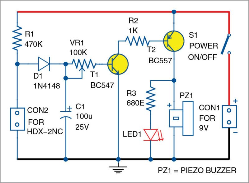
Circuit diagram of the simple suitcase-lift alarm is shown in Fig. 1. It is built around HDX-2NC, which is connected across connector CON2, transistors BC547 (T1) and BC557 (T2) and a piezo buzzer (PZ1).

Normally, vibration sensor terminals are shorted internally. When the suitcase is lifted, sensor terminals momentarily open. This allows capacitor C1 to charge through resistor R1 and diode D1. Discharging path is through VR1 and T1.

When T1 and T2 conduct due to charged C1, LED1 glows and the buzzer sounds. Alarm duration can be set using VR1.
Use a piezo buzzer with internal oscillator for the alarm sound. The circuit works off a 9V battery, which is connected across connector CON1.
Construction and testing
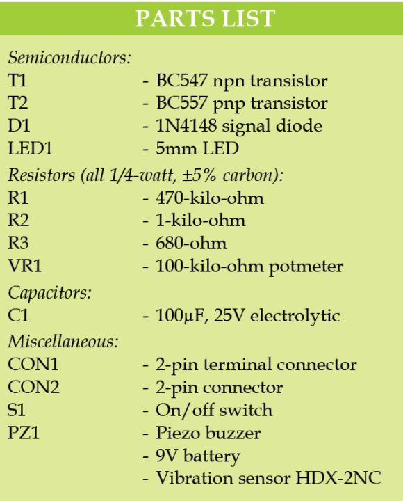
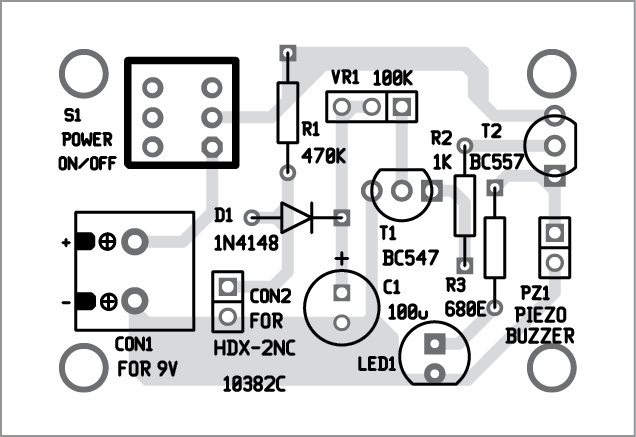
A single-side PCB pattern for the simple suitcase-lift alarm is shown in Fig. 2 and its component layout in Fig. 3. After assembling the components on the PCB, house the circuit in a small box.


Download PCB and component layout PDFs: click here
Check the circuit’s working before you put it in your suitcase for use as an alarm. Switch on the circuit and place it in a suitable place inside your suitcase.


Where can i get the PCB or the complete PCB with components ? Please help me to build this project.
Dear Kalyan,
All the information regarding the project is given within the article.
How it works when the suit case is lifted
sir can u explain the working in detail
Dear Abhishek, all the information regarding the project is already given in the article.
sir, post an image of hardware of project and also post an image of sensor which used with working…..
The vibration sensor HDX-2NC used in this project can be found from the link given here:
https://www.amazon.com/HDX-2-Normal-Vibration-Sensor-Switch/dp/B00SWK1BDK
Sir can u explain the input & output & working detail
good day sir,
I like this circuit set up and would like to try it.
how can the sensitivity triggering the alarm be increased or decreased?
Thanks for the feedback! The sensitivity depends on the sensor used here. In this example, the sensitivity cannot be increased or decreased with the current design.
Battery will always in discharging mode thru’ resistor R1 and S1.
Hi! Does anyone have a simulation of this? Or have tried this? I’ve tried this before but I can’t seem to make it work.
Thanks!