


 When bathing a baby, it’s important that the water is neither too cold nor too hot. You test the water by dipping your fingers in the bath tub before putting the baby into it. Here is a simple circuit that indicates the water temperature, helping you to use water that is just right for your baby. Limit points for high and low temperatures can be set to any level. So this circuit can also be used to ensure optimal temperature for a room, greenhouse, pool, geyser, fish-tank or freezer.
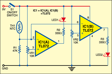
Fig. 1 shows the circuit of the water temperature indicator. The circuit is built around dual op-amplifier IC TL072 (IC1), which is configured in comparator mode. The sensor used in the circuit is a thermistor—a two-pin device whose resistance varies with temperature. Thermistor TH1 has a resistance of 47 kiloohms at room temperature (25°C). Resistor R1 of the same value as TH1 is connected in series with TH1.
At 25°C, the resistance of the thermistor is around 47 kilo-ohms. So the voltage at pin 2 of the first op-amplifier IC1(A) is approximately half the supply voltage. As the water temperature increases, the resistance of the thermistor decreases, while the resistance of R1 remains unchanged. As a result, the voltage at input pin 2 of IC1 increases. Conversely, a fall in the temperature of TH1 causes the voltage to fall at pin 2 of IC1.

The reference voltage at pin 3 of IC1 is set by using preset VR1. It is set such that at room temperature, the voltage at pin 2 (inverting input) is lower than the voltage at pin 3 (non-inverting input). As a result, the output at pin 1 is high and LED1 doesn’t glow.
IC1(B) is the second opamp, with pin 6 as the input. The reference voltage for the upper limit of water temperature at its pin 5 is set using preset VR2. It is set such that when the temperature is below the upper limit, the voltage at pin 5 is higher than the voltage at pin 6 and LED2 glows. But when the temperature goes above the upper limit, the output of IC1(B) at pin 7 goes low and LED2 goes off. This means as the temperature rises beyond the upper limit, the voltage at pins 2 and 6 falls. When the voltage at pin 6 is less than the voltage at pin 5, the output becomes high and LED2 glows.

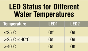
The LED status for different water temperatures is summarised in the table. The ideal water temperature to bathe the baby is when both the LEDs glow.
The circuit requires 9V for operation, which you can get either from six AA-size or AAA-size cells in a battery holder or from a 9V PP3 battery.
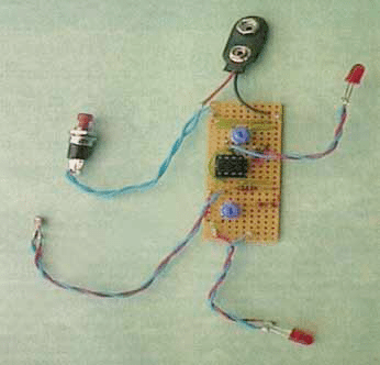
Assemble the circuit on a general purpose PCB and enclose in a suitable cabinet. The circuit board is small enough to fit inside the miniature plastic enclosure of a handheld gadget. If you want to build it as a probe-type instrument, drill a hole at one end of the enclosure and glue a short length of stiff plastic tubing (fish-tank aerating tube or a scrap of model-maker’s polystyrene tube). Extend the thermistor out from the circuit using two insulated wires. Glue the thermistor to the end of the tube. Apply plenty of glue to the thermistor so that it dries to form a waterproof seal.
For low-temperature setting, put the thermistor in a glass of tepid water. Adjust VR1 until LED1 goes off For high-temperature setting, put the thermistor in a glass filled with hot water. Adjust VR2 until LED2 goes off. Test your settings by immersing the probe in water within the acceptable temperature range. In this case both the LEDs should glow. Fig. 2 shows the author’s prototype.