 A function generator is an essential equipment used by design, and test and measurement engineers as well as DIYers. Most of the function generators available in the market are expensive and bulky to carry and use.
To simplify this issue, I have made a function generator that is more affordable, portable and easy to use wherever testing functionality is required. The function generator can seamlessly perform basic functions of a conventional function generator including different waveform generation, and frequency and phase changes of waveforms.
Bill Of Materials

Coding
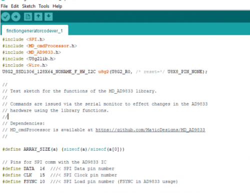
Install the library for the AD9833 chip from Analog Devices and the U8g2 library for the OLED display. To do this, open the Library Manager located in the Sketch menu option, search the respective libraries and install them.
To begin coding, initialise the libraries for the OLED display and AD9899 chip. Then define the pin numbers for the sensor’s SPI pins.
After this, create the setup function along with other functions and a loop for handling the commands from serial terminals for changing the waveform to generate the desired sine waves, triangle waves, square waves, etc. You can also attach a potentiometer for changing the phase and frequency of the waveforms.

Then create a loop for displaying and updating the values of current waveform frequency and phase values on the OLED display.

Designing
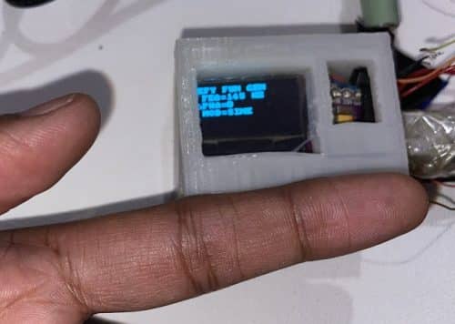
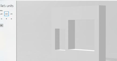
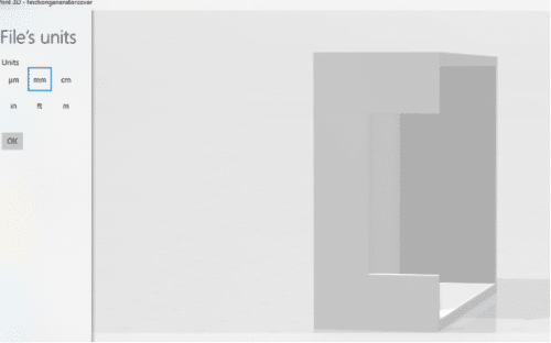
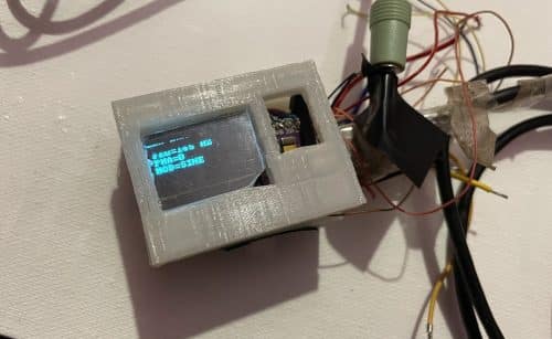
To design the outer body of your tiny function generator, you can use any wooden or plastic box, or custom 3D print it. As shown in the picture below, I made a small section for displaying the OLED screen and affixed an acrylic glass to protect the OLED display.
Underneath the front cover, I made a cavity for the USB port connection of the function generator. I also made a small cavity beside the OLED display cavity to adjust the potentiometer for changing the frequency. Note that I did not use the same point in the cavity for connections as I’m using serial port to change the waveform frequency.
Connection
Solder the chip and OLED display as shown in the below circuit diagram.
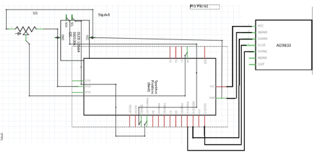
After that, assemble everything in the case that you designed and connect the wire of the output signal from the function generator.
Testing
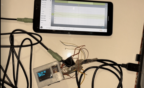
Now connect the device with a PC and open the serial terminal. Send the command to the device about the wave frequency and phase you wish to generate.
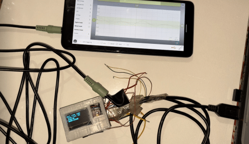
Then connect the output of the device to an oscilloscope to see the waveform generated. For the project demo, I used a smartphone to test the device. You can also use a smartphone as a basic oscilloscope and see the waveform on it. Simply connect your smartphone audio input/output port with an aux cable to the function generator.
However, do note that the generated waveform will not be accurate and will have noise. But it’s fine for testing purposes. After selecting the waveform type and its frequency, you can output the wave.
Congrats !! You have made a small function generator that can be carried anywhere for testing and designing purposes. It is also equipped to perform basic functions of a traditional functional generator such as triangular waves, square waves and sine waves.


