JULY 2012: With this circuit built, boxed up and installed in your bicycle, you can look forward to safely riding your cool bicycle at night. The circuit ensures that the bicycle lights remain ‘on’ for a little while after the bicycle has come to a standstill.
The circuit is 6V, 3W dynamo compatible and its working is very simple and straightforward. When the bicycle dynamo is idle, it connects the bicycle lights source to the reservoir battery pack until the dynamo starts generating voltage again. The circuit also prevents the light source against high power when the dynamo is running, and uses the available surplus power to recharge the battery pack.
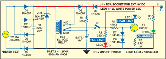
As the diagram shows, the standard bicycle headlight bulb is replaced with a compact 1W generic white LED module. Likewise, the tail lamp is replaced with a 10mm red LED. The battery pack is a combination of five 1.2V, 600mAh Ni-Cd cells, connected in series to produce an output of 6V DC.

When you ride the bicycle, the dynamo touching the wheel spins around and diodes D1, D2, D3 and D4 form a bridge via which buffer capacitor C1 charges. When the dynamo voltage is sufficiently high, the low-current 5V relay energises and the DC supply available across C1 is routed to the headlamp (LED1) driver circuit (and to the tail lamp LED) through power switch S1. At the same time, the Ni-Cd battery pack charges through components D5 and R1.
When the bicycle is not driven and the dynamo is standstill, the relay is no longer energised. Therefore the bicycle lights (LED1 and LED2) are powered by the Ni-Cd battery pack. Diode D5 prevents the Ni-Cd battery from slowly discharging via the circuit when the bicycle is not used (switch S1 should then be opened).

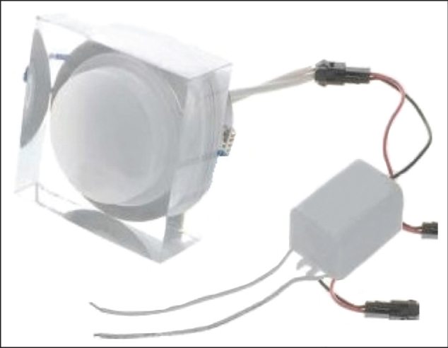
When white LED is used as the bicycle headlight (with supporting optics), the result is quite good. However, the viewing angle and the brightness of LEDs vary inversely. A wider angle will result in lower brightness in any given direction as the total light output of the LED is spread over a larger area. For headlight applications, a 20° viewing angle is appropriate. This narrow beam aspect of many of the white LEDs has a downside too. The narrower the LED beam, the dimmer it will appear when viewed off angle!
As shown in the circuit diagram, the headlight unit includes a 1W white LED and a small driver section. The driver section is, in fact, a constant-current driver realised using medium-power npn transistor BD139 (T1). The charger jack (J1) allows you to recharge the Ni-Cd battery pack with the help of an external DC power source such as a travel charger (9V) or a miniature solar panel (6V). The 12V zener diode (ZD1) in the circuit is added deliberately to protect the entire electronics (excluding the external charger) from an accidental over-voltage condition that may occur when the dynamo is running very fast.
Note. Bicycle dynamos are alternators equipped with permanent magnets. These are typically clawpole generators delivering energy at rather low RPM. The sidewall-running dynamo (aka bottle dynamo) is the most popular type.
Most bicycle dynamos are rated 6V, 3W (500 mA at 6V). However, the power of a dynamo light system depends somewhat on the speed. In a standard bicycle lights system, the power is zero at standstill. At moderate speed it’s about 3W, and at very high speed it’s just a little more than 3W.
Some manufacturers include limiting zener diodes or other forms of overvoltage protection, to protect the light bulbs. Experienced hobbyists usually remove this internal protection circuitry to get more supply output from the same dynamo!