


Most textile retail stores have trial/changing rooms for customers to try on new clothes before buying them. These rooms are illuminated all day long, irrespective of whether these are being used or not. This leads to wastage of electricity.
Presented here is the circuit that turns the light on only when someone enters the room. This circuit also indicates the occupancy status of the room. It can be used for bathrooms and public toilets as well, besides some other places.
Circuit and working
The circuit diagram of the smart light is shown in Fig. 1. It is built around 5V voltage regulator 7805 (IC1), AVR microcontroller (MCU) ATtiny85A (IC2), opto-coupler PC817 (IC3), PIR sensor, common-cathode bi-colour LED (BICO1), normally-open magnetic reed switch (S2), 12V single-changeover relay (RL1), two BC547 npn transistors (T1 and T2) and a few other components.


IC2 is the brain of the circuit, which turns on/off the light connected through the relay based on input state. Presence of a person in the room is detected by the PIR sensor, whereas door status is detected by the reed switch. If any motion is detected by the sensor, its output goes high. Otherwise, the output remains low.
Reed switch contacts remain open when the door is open. When door is closed, contacts get closed. Statuses of the PIR sensor, reed switch and relay are given in the table. It gives input and corresponding output statuses for every action.

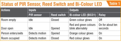
If the room is unoccupied and the door is closed, the LED emits green light. The relay switches off to save power. If someone opens the door, the LED emits red and green colours alternately until the person enters the room.
The relay turns on for about ten seconds and then it turns off. Light bulb (Load1) connected through the relay illuminates during this period. If a person enters the room within ten seconds after the door is opened, the relay gets activated and LED emits orange colour until the door is closed. Thereafter the LED emits red colour, indicating that the room is occupied and the door is closed.
The MCU is isolated from the relay power supply using opto-coupler IC3. The relay is turned on/off through the opto-coupler. This protects the MCU from any disturbance in the 12V supply for the relay. Freewheeling diode D1 suppresses the induced high voltage produced by the relay coil when relay RL1 is turned off. In the circuit, Load1 is the main light, while Load2 is the optional standby light.
Software program
The source code (trial_room.ino) is developed using Arduino IDE. By default, Arduino IDE does not support ATtiny85A and, hence, we need to add ATtiny library to Arduino IDE.
Adding ATtiny support
To add ATtiny support to Arduino IDE, follow the steps given below.
1. Open File→Preferences and in Additional Boards Manager URLs enter https://raw.githubusercontent.com/damellis/attiny/ide-1.6.x-boards-manager/package_damellis_attiny_index.json
2. Open Tools→Board→Board Manager. Scroll down the list and find ATtiny by Davis A. Mellis. Click on that and install it. Now, ATtiny will be listed in Boards menu.
3. Select ATtiny25/45/85 under Tools→Board. Select ATtiny85 under Tools→Processor. Now, select 8MHz (internal) under Tools→Clock.
Arduino as ISP
To make Arduino Uno work as ISP programmer, connect Arduino Uno to the PC/laptop and open Arduino IDE. Make sure you select Arduino/Genuino Uno as your board. Open Arduino ISP example sketch, and upload Arduino ISP sketch to Arduino Uno. Arduino Uno is now an ISP programmer.
Programming ATtiny85A
By default, ATtiny85A runs at 1MHz. To make it run at 8MHz, select Tools→Burn Bootloader. Make sure that Arduino Uno board is programmed as ISP and it is connected with ATtiny85A through ISP pins. Now, upload the source code (trial_room.ino) to ATtiny85A using Arduino Uno board.
Construction and testing
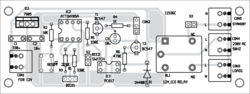
An actual-size PCB layout of the smart light is shown in Fig. 2 and its components layout in Fig. 3. After assembling the circuit on the PCB, enclose it in a suitable box.

Download PCB and component layout PDFs: click here
Download Source Folder: click here
A small magnet bar or disk is fixed on the door and reed switch S2 is fixed on the door frame. Connect reed switch to the PCB using two wires. The reed switch and magnet must face each other, so that when the door is closed, S2 gets activated by the magnet.

Load1 is the bulb used for the smart light, while Load2 is the standby bulb. You may enable the standby low-power bulb to be continuously on till S3 is on and relay is not energised. (Relay RL1 on means Load1 is on.)
Samiuddhin is B.Tech in electrical and electronics engineering. His interests include LED lighting, power electronics, microcontrollers and Arduino programming.


There is no any source code in this article? PLease check it
Hi Amin, thank you for your comment. We have updated the article with Source Code.
Hi…will u provide gerber file of pcb…
Please send your request to [email protected]