


 Simple loop burglar alarms sound whenever the loop breaks. What if a clever thief comes to know of the working of this alarm? He may simply short the loop by using some other conductor and then cut the shorted portion of the loop without any problem. Here is the circuit of a smart loop burglar alarm that overcomes this drawback by using a sensing resistor (R) in the loop. The sensing resistor has to be kept inside the area to be protected (say, a room).
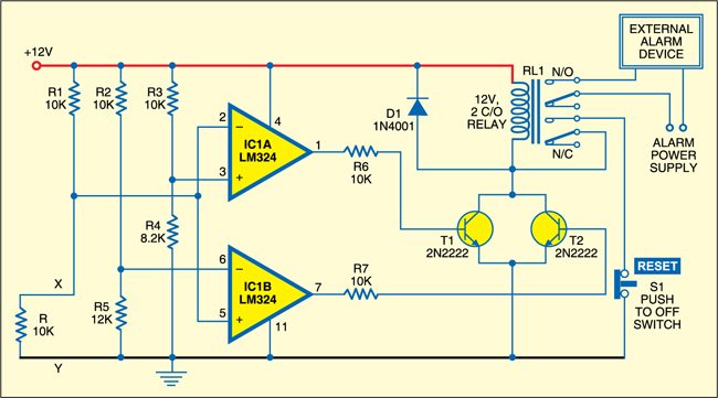
Fig. 1 shows the circuit of the smart loop-type burglar alarm. This circuit is built around quad op-amp LM324 and a few discrete components. Two op-amps of the LM324 are configured as voltage comparators.
Resistors R and R1 divide the 12V DC power supply equally. The resulting 6V is applied to the inverting input of the first op-amp (IC1A) and the non-inverting input of the second op-amp (IC1B). The non-inverting input of the first op-amp (IC1A) is kept below 6V and the inverting input of the second op-amp (IC1B) is kept above 6V. As a result, in normal condition, the outputs of both the op-amps remain low.

When the thief shorts the loop outside the area to be protected, the output of op-amp IC1A goes high, transistor T1 conducts and relay RL1 energises to sound the alarm.
Also, when the thief breaks the loop, the output of op-amp IC1B goes high, transistor T2 conducts and relay RL1 energises to sound the alarm. Thus the alarm sounds when the loop is shorted or cut.

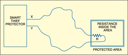
Assemble the circuit on a general-purpose PCB and enclose in a suitable cabinet. The relay should be 12V, 2C/O type having contacts of suitable current rating. Use a regulated 12V DC power adaptor or a 12V battery to power the circuit. Before connecting the circuit to the power supply, check the assembled PCB for proper soldering of the components. Connect the first C/O contacts of the relay to the 230V AC bell (for alarm) and the second C/O contacts to reset switch S1. Mount switch S1 on the front panel of the cabinet. Use a thin wire for loop connection. Don’t forget to connect sensing resistor R in series and place it in the area to be protected (refer Fig. 2).
