 To switch on the mains voltage, either a mechanical switch or a relay offers a simple solution. However, the relay and its associated components occupy a lot of space and cannot be accommodated in a standard switch box. The smart switch circuit, shown here, offers a better alternative.
Smart switch circuit
It is nothing but an ‘on’/‘off’ controller and uses an electronic circuit that behaves like a normal switch. A flat push button control provides an aesthetic look to your switch panel.
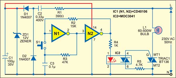
The switching circuit comprises an optocoupler circuit that receives input from a bistable switch formed by a couple of Schmitt trigger gates that control a triac. The load can be switched on/off by simply pushing the push button switch for a brief period. Every time the switch receives a push, the optocoupler toggles the triac. A special zero-crossing detector in the optocoupler suppresses radio interference, unlike the arbitrary phase switching.

Since mains is not isolated, use a good quality push button switch with proper insulation to avoid lethal shock. Make sure that the triac can handle the current you are going to draw through it. If required, several push buttons can be wired in parallel to allow toggling of the triac from different locations.
The article was first published in September 2005 and has recently been updated.