


Here is a low-cost circuit that automatically extracts solder fumes while you assemble a circuit, thereby saving you from inhaling the same. The solder paste gives off toxic fumes, which could pose a potential health hazard if not controlled. Those working closely with electronic components are at a higher risk of fumes being inhaled.
Place this compact unit close to the circuit board and it will extract all the fumes from the immediate working area, leaving smoke-free surroundings. It is fully automatic and turns on a fan when the soldering iron is kept in the holder unit after making a solder joint. The fan automatically turns off after a few seconds. The automatic working of the unit is convenient as the soldering work is intermittent.
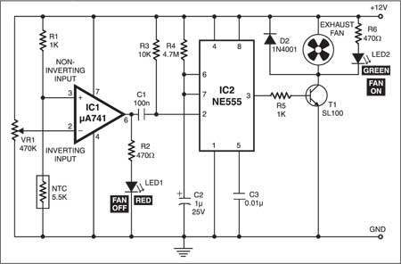
The circuit (Fig. 1) is designed around popular op-amp µA741 (IC1), which is configured as a comparator. Its non-inverting input (pin 3) is held high by a potential divider comprising resistor R1 and an NTC thermistor; NTC refers to negative temperature coefficient. The inverting input (pin 2) of IC1 is supplied with a reference voltage by preset VR1.

Initially output pin 6 of IC1 is high. Set the voltage at inverting input pin 2 below the voltage at non-inverting input pin 3. When the hot soldering iron is placed close to the thermistor, the resistance of the thermistor falls, dropping the voltage at the non-inverting input of IC1 below the voltage at pin 2. The resulting output at pin 6 goes from high to low and triggers the monostable for a prefixed time (here approximately 30 seconds) to switch on the exhaust fan. This condition is maintained as long as the soldering iron is placed close to the thermistor.
The output of IC1 is fed to trigger pin 2 of monostable IC NE555 (IC2) via capacitor C1. IC2 is designed as a standard monostable and its trigger pin 2 is held high by resistor R3. When the output of IC2 goes low, it cuts off transistor T1 and the fan is switched off.

When the soldering iron is removed from the unit, the thermistor cools and its resistance increases again and subsequently the output of IC1 goes low. This sends a low pulse to the trigger of IC2 and its output goes high. As a result T1 is biased into conduction and the fan is supplied virtually the full 12V supply and it turns on.
Resistor R5 prevents the excessive base current from flowing into the transistor. The timing components of the monostable are resistor R4 and capacitor C2. With the specified values, the ‘on’ time for the fan is around 30 seconds. Diode D2 protects the transistor from back e.m.f. LED1 and LED2 indicate the exhaust fan’s ‘off’ and ‘on’ conditions, respectively.
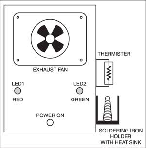
The circuit can be constructed on a simple Vero/perforated board. A 12V DC, 500mA mains adaptor is used to power the circuit. House the circuit in a metal case. You can use a small heat-sink (as used in power transistors) to make the set-up for keeping the soldering iron.
Fix the thermistor close to the heat-sink. The thermistor leads should be well insulated with heat-resistant sleeves. Fix the fan in the same fashion as an exhaust fan to pull away fumes from the working area.
After assembling the circuit, adjust VR1 until green LED2 turns off. When you take the hot tip of the soldering iron near the thermistor, green LED2 turns on. The setup is now ready for use.

Hi, can you post the design for your circuit, i.e., how did you choose your resistance values?
We may not be posting the design steps for this circuit. However, you may refer to related topic in Resources section on this website or some other websites.
sir, I am suhasini.challamalla doing my graduation in final year eee. I am interested in designing smoke extractor circuit I have purchased all the components required for it, but only the problem is NTC 5.5K is not available in the market but the range available from 10K. so I connected the circuit by using 10k, it was not working. so, sir please kindly give me suggestion on it to overcome this problem.
We done the circuit by using 10k NTC instead of 5.5k NTC because of non availability, but the circuit is not operating please give me suggestion on it.
Hi, we tried your circuit, is there any chance to replace NTC with any other element
You can try it using 10K NTC instead of 5.5K NTC. First, check the status of LED connected to output pin 6 of IC1.
hi..we tried using 10k NTC instead of 5.5K NTC.But first, the status of LED connected to output pin 6 of IC1 is OFF instead the GREEN LED is ON . Is there any change in the value of VR1(470K) if the 10k NTC is used or else VR1 is still 470k??
hi..we tried using 10k NTC instead of 5.5K NTC.But first, the status of LED connected to output pin 6 of IC1 is OFF instead the GREEN LED is ON . Is there any change in the value of VR1(470K) if the 10k NTC is used or else VR1 is still 470k??
The value of VR1 will remain same but the output level at pin 6 of IC will change as per the values of NTC and VR1. You can vary VR1 slowly and observe the changes at pin6.
Your circuit is not working.
Can you please tell what should be expected voltages at
1. Red led when it is ON and OFF
2. Green LED when it is ON and OFF