


Monostable mode. In this mode, the 555 timer acts as ‘one-shot pulse generator,’ producing a single pulse when triggered. As shown in Fig. 3, the external capacitor is initially held discharged by a transistor inside the timer. The circuit triggers on a negative-going input signal when its level reaches 1/3Vcc. Once triggered, the circuit remains in this state until the set time has elapsed, even if it is triggered again during this interval.
Download Source Code: click here
Bistable mode. In this mode, the timer acts as a simple flip-flop, which can be set and reset using pins 2 and 4, respectively.

Astable mode. When the circuit is connected as shown in Fig. 5 (pins 2 and 6 connected), it triggers itself and free runs as a multivibrator. The external capacitor charges through resistors Ra and Rb and discharges through resistor Rb only. Thus the duty cycle can be precisely set by the ratio of these two resistors. In astable mode of operation, capacitor C charges and discharges between 1/3Vcc and 2/3Vcc. The charge and discharge times, and therefore frequency, are independent of the supply voltage.
Matlab program
The program presented here can be used to design a 555 timer for astable operation. For astable operation, the major design parameters are duty cycle and frequency. The graphic user interface designed in Matlab environment takes the desired frequency, duty cycle and value of Rb as input to calculate rest of the timing components’ values.

The flow-chart of the program is shown in Fig. 6.
Testing
Follow the steps below to run and test the software:
1. Download the source code and open the folder that contains the files Tmmnew.m, Tmmnew.fig, Tmmnew.asv and 555circuit.jpg
2. Open Tmmnew.m in Matlab software.
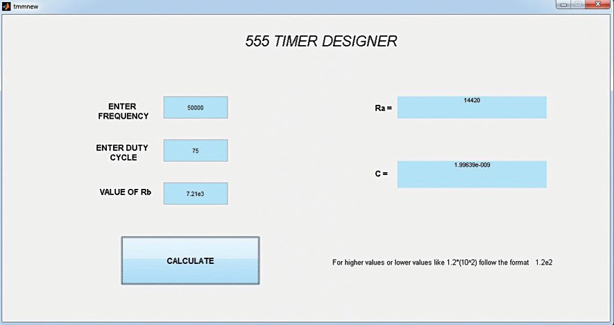
3. Run the software using ‘Run’ button from the toolbar. You will see a GUI similar to the one shown in Fig. 1.
4. An image of the 555 timer wired in astable mode will also open in parallel for reference.
5. Now enter the frequency, say, 50000 (in Hz unit).
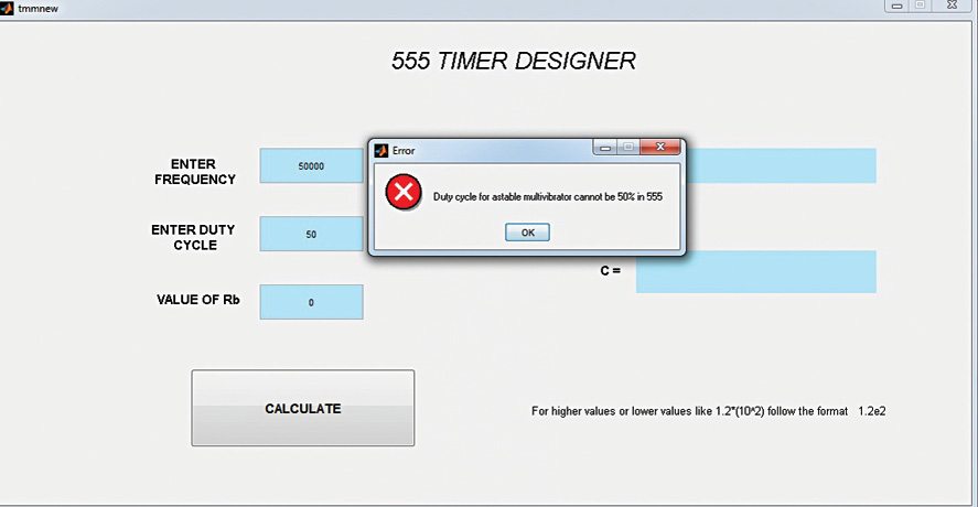
6. Enter duty cycle, say, 75 (this will be in percentage). If you enter a duty cycle less than or equal to 50, the software shows an error, as shown in Fig. 8.
7. Now enter the value of resistor Rb preferably in kilo-ohms (say, Rb=7.21e3) for a good design.
8. Press ‘Calculate’ button.
Now you should have the values for Ra and C. All you need to do is to assemble the circuit as per Fig. 5 using the values of timing components calculated through the software and you will get the desired duty cycle and frequency at the output.
The author is an R&D engineer at Hitech Electronics. He is a BE in electronics and telecommunication from MIT, Pune. His Interests include MATLAB, LabVIEW, communication and embedded systems
