Power transformers are essential part of a power system network. A transformer is used at the transmission side to step up the voltage level and at the distribution side to step down the voltage. A thorough knowledge of the transformer’s performance under various operating conditions is fundamental in determining the power system reliability.
One of the major issues in maintaining the power-supply quality is the disturbance caused by transformer energisation. Inrush current is the magnetising current that occurs during switching of an unloaded or lightly loaded transformer onto the electric grid. Due to non-linear magnetic characteristic of the transformer core, transformer energisation results in inrush currents of a high magnitude, which, under certain conditions, may reach several times the rated current of the transformer.
Inrush current is highly non-sinusoidal in nature and thus rich in harmonics. It may damage the transformer itself, affect relay operation and reduce power quality due to the presence of harmonics. Inrush current is a problem as it interferes with the circuit operation; in a digital world, there is zero tolerance for power interruptions.
So accurate determination of inrush current is desirable to predict potential problems when an unloaded or lightly loaded transformer is switched onto the power supply. This is essential to devise correct methods to curb inrush current.
Factors affecting the magnetising inrush current
The transient electromagnetic state causing inrush current in a transformer when it is connected to the power supply, depends on the following factors:
- Voltage angle when the transformer is switched on
- Magnitude and polarity of residual flux in the transformer core at the instant of energisation, that is, residual flux density (Br)
- Total resistance of the primary winding circuit including system resistance
- Inductance of the air-core in between the energised winding of the transformer
- Geometry of the transformer core, that is, axial length of the energised winding (Hw); area enclosed by mean turn of the winding, that is, mean diameter of the energised winding (Dm); and number of turns of the excited winding
- Maximum flux-carrying capability of the core (Bm)
- Saturation flux density of the core (Bs)
- Capacity of the transformer and its primary/excited voltage value
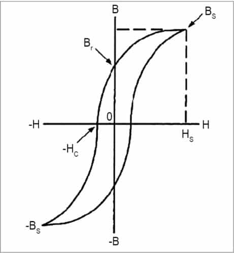
- A typical hysteresis curve showing relationship between magnetic field strength (H) and flux density (B) for the transformer core material is shown in Fig. 1.
Residual flux density (Br)
In Fig. 1, the hysteresis loop clearly shows residual flux density. When a transformer is de-energised, some level of flux remains in the transformer core. The actual value of flux is based on the alignment of the steel’s magnetic moments, and can be found from magnetic hysteresis loop of the transformer core. Residual flux may therefore be positive or negative in value, and is typically 30-80 per cent of the core’s maximum flux. When the transformer is energised, this residual flux is added to the flux driven by the exciting voltage.
Saturation flux density (Bs)
The hysteresis loop shows when a high magnetising force is encountered, a point is reached where further increase in H does not cause an increase in B. This point is known as the saturation point of that material. Saturation flux density Bs and magnetising force required to saturate the core (Hs) are shown through dashed lines in Fig. 1.
Peak flux density (Bm)
This is the peak value of designed steady-state flux density in the core.
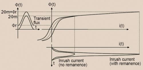
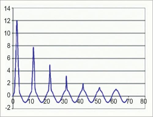
The inrush current phenomenon including the effect of residual flux is shown in Fig. 2. A typical inrush current waveform is shown in Fig. 3.
Inrush current model
In this software, the technique suggested by T.R. Specht, popularly known as Specht technique in transformer engineering books, is used to calculate the peak value of inrush current for selected number of cycles. The procedure is as follows:
Step 1
Inrush current is calculated for the worst-case condition, considering that the transformer is energised at the instant when voltage is zero and residual flux is in the same direction as the initial flux change. This gives the maximum possible value of inrush current.
Once the core saturates, inrush current gets limited by air-core reactance Xs, which is calculated as:

where N is the number of turns of the excited winding, µ0 permeability of free space, Aw area inside the mean turn of excited winding {= ( /4)×(mean diameter)2} and hw height of the energised winding.
Step 2
Angle at which the core saturates is given as:
θ=k1×cos-1 (Bs-Bm-Br/Bm)
where Bm is peak flux density in Tesla, Br residual flux density in Tesla and Bs saturation flux density of the core material in Tesla.
For a core made of cold rolled steel, Br=80% of Bm
For hot rolled steel, Br=60% of Bm
k1= correction factor for saturation angle
That is, k1= 0.9
Step 3
Inrush current peak for the first cycle on single-phase basis is calculated as:

where V is rms phase value of the primary/excited winding and k2 correction factor for the peak value (=1.15).
Step 4
Residual flux density at the end of the first cycle is calculated in this step. The residual component of flux density reduces due to damping in the circuit provided by the resistance of the system. The new value of residual flux density is calculated as:

where k3=correction factor for the decay of inrush=2.26
Steps 2 through 4 are repeated to calculate the peak value of inrush current for all the subsequent cycles.
Effect of switching angle on the peak value of inrush current
The key factor in determining the magnitude of the magnetising inrush current is the switching angle of voltage source. The following formula, which takes into account the effect of switching angle and circuit resistance to predict the first peak of inrush current, has been used:

where R is the total resistance including system resistance and is the initial phase angle of the voltage source.
Features of the software
The software presented here performs inrush current analysis of either a single-phase or three-phase transformer using the above-mentioned mathematical model and predicts the following characteristics:
1. Calculates the peak value of inrush current for individual cycles and plots them on a graph, thus providing inrush current envelope
2. Calculates the effect of switching angle on the peak value of inrush current
3. Calculates the magnitude of harmonics of different orders generated due to inrush current and determines total harmonic distortion (THD) due to inrush current
The software presented here is developed in Java Standard Edition (SE) using the software development kit (SDK) version Java 2 SDK, SE v1.8.0_60.
The software is user-friendly with the front end as a GUI, which is a Java Swing based class through which the user interacts and selects various options to run the program and enter the data. At the back end, these options are processed in the code written in core Java. Results are displayed using Java Swing features. That is, inrush current graph is plotted using graphics feature of Swing and results of the effect of switching angle and harmonic analysis are displayed in tables.
The program uses the following files:
inrush_4a.java
This file contains following classes:
inrush_4a
This is the main class. It is used to accept options from the user and process them. Options include Enter Transformer Data, Display Inrush Current Graph, Calculate Effect of Switching Angle and Harmonic Analysis.
EvenOddRenderer.class
This class is used to set properties of the table in which the result of effect of switching angle and harmonic analysis will be displayed.
Main.class
In this software, a provision has been made to allot an ID number to each transformer job. The generateRandomString( ) function of main.class is used to generate the transformer ID number at the time of entering transformer data.
LineChart_use.java
This file contains the class LineChart_use, which facilitates plotting of inrush current graph.
Steps to run the program
In order to run the program, batch file inrush4a.bat is created. Batch file is an executable file. It contains a set of commands to run the program. The advantage of using the batch file is that you need not set the address of the directory, files and other resource files again each time you run the program. These issues are handled by batch file.
inrush4a.bat batch file contains the following commands:
@ECHO OFF
set path= C:\Program Files (x86)\Java\
jdk1.8.0_60\bin; %PATH%;%path%
javac inrush_4a.java LineChart_use.java
java inrush_4a
Here, ECHO OFF command does not allow the command prompt to appear on the screen. When @ is prefixed, echoing of a line on the screen is prevented. Therefore @ECHO OFF command prevents echoing of batch file contents on the screen.
Path is an environment variable specifying a set of directories where executable programs are located. It is a series of directories separated by semicolons (;). Microsoft Windows looks for programs in Path directories in order, from left to right, and executes them. In this batch file, the path variable is set to JDK bin directory, where executable commands javac (to compile the program) and java (to run the program) are located.
javac command is used to compile the program. The program is distributed among two files, inrush_4a.java and LineChart_use.java, both of which are compiled together using the command:
javac inrush_4a.java LineChart_use.java
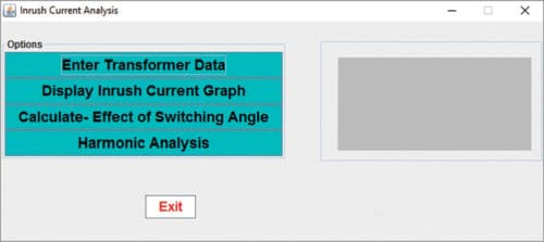
In order to run the compiled java inrush_4a program, double-click inrush4a.bat file or right-click the icon of inrush.bat file, and select ‘Open.’ A window will appear on the screen with the following options:
1. Enter Transformer Data
2. Display Inrush Current Graph
3. Calculate-Effect of Switching Angle
4. Harmonic Analysis
This is the main window (Fig. 4).
The desired option can be selected by clicking.
Enter Transformer Data
First of all, enter data of the transformer for which inrush current analysis is to be done. Click Enter Transformer Data in the main window. Now, another window is displayed on the screen, wherein you need to fill in transformer details under following 13 fields:
- Transformer ID No {not to be entered}
- Transformer Capacity. Here the transformer capacity in kVA is to be entered
- Primary/Excitation Voltage. Here enter voltage of the primary/excitation side, that is, voltage of the side that is connected to the source, in kV. In case of a 3-phase transformer, enter the phase value of the voltage. For example, if it is a 132kV/33kV Star/Delta (Y/D) transformer that is excited from the primary side, the voltage value will be 132/3=76.21kV.
- Secondary Voltage. Here enter voltage of the secondary side in kV. In case of a 3-phase transformer, enter the phase value of the voltage. For example, if it is a 132kV/33kV Star/Delta (Y/D) transformer, secondary-side voltage will be 33kV.
- Power Frequency. Here select power frequency of the supply from the drop-down menu. It may be 50Hz or 60Hz. For example, it is 50Hz for India and 60Hz for USA.
- Number of Turns of Primary/Excitation Winding. Here enter the number of turns of the winding that is connected to supply side.
- Primary/Excitation Winding Height. Here enter axial height of the primary/excitation winding in mm.
- Primary/Excitation Winding Mean Dia. Here enter mean diameter of the excitation winding in mm.
- Resistance. Here enter resistance of the primary/excitation winding including resistance of the system, that is, resistance of the line between source and transformer, in ohms.
- Core Material. Usually, the transformer core is made of grain-oriented steel. Select core material of the transformer from the drop-down list as ‘Hot Rolled Steel’ or ‘Cold Rolled Steel.’
- Saturation Flux Density. Here enter saturation flux density (Bs) of the core material in Tesla.
- Peak Flux Density. Here enter peak value of designed steady-state flux density (Bpeak) of the core material in Tesla.
- Cycles for Inrush Current Calculation. From drop-down menu, select the number of cycles for which inrush current is to be calculated and plotted. The number of cycles may be selected between 5 and 50. This window is shown in Fig. 5.
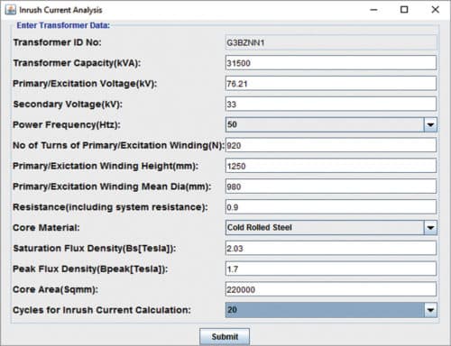
14. Core area. Here the core area of transformer is entered in sqmm.
Once you enter transformer data, click Submit. In case the entered data is correct, the data entry screen disappears and the main window appears on the screen.
The program automatically checks data entry. Data is accepted only if none of the fields is left blank, and numeric data is entered wherever required. For example, if non-numeric data is entered in the field for Transformer Capacity, it will not be accepted.
Display Inrush Current Graph
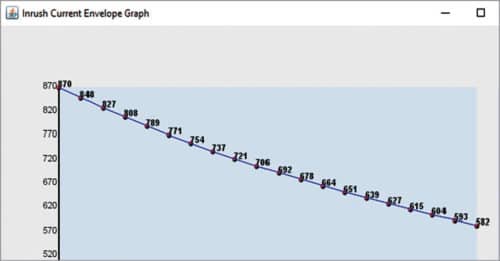
If this option is selected, the graph showing peak value of inrush current in each cycle is plotted. The number of cycles is given on x-axis, while peak value of inrush current is given on y-axis. Peak value of inrush current for each cycle is written on the graph itself. Brief analysis of the transformer’s inrush current characteristics also pops up on the screen.
Inrush current is calculated on per-phase basis. In case of a 3-phase transformer, during the inrush condition, only one phase has large inrush current-that is, the phase that gets switched at the worst or near worst instant of voltage switching (meaning when switching angle is 0 degree or near 0 degree). The software calculates this value of inrush current.
Calculate-Effect of Switching Angle. If this option is selected, value of the first peak of inrush current is displayed in a table with respect to switching angle of the source voltage for the worst case, that is, when residual flux is in the direction of flux change. Inrush current value is displayed for switching angle of 0 degree, 30 degrees, 60 degrees and so on up to 180 degrees in a difference of 30 degrees. It can be observed from these values that inrush current decreases when switching angle increases.
Harmonic analysis
If this option is selected, the following information is displayed on the screen in tabular form:
1. Peak value of inrush current for DC component (0Hz), fundamental frequency, harmonics of second order up to tenth order and individual distortion IDn (magnitude of the nth harmonic as a percentage of the fundamental)
2. Total harmonic distortion (THD) in percentage
Software testing
Software has been tested for various examples available in standard textbooks of transformer engineering including the test problem example given below:
Transformer data
- Capacity: 31500kVA
- Vector group: 3-phase, Star/Delta
- Primary/excited winding voltage: 132kV (value entered on per-phase basis: 132/ 3, i.e., 76.21kV)
- Secondary winding voltage: 33kV
- Power frequency: 50Hz
- Number of turns of primary/excited winding: 920
- Primary/excited winding height: 1250mm
- Primary/excited mean dia: 980mm
- Total resistance (including system resistance): 0.9 ohm
- Peak flux density (Bm): 1.7 Tesla
- Saturation flux density (Bs): 2.03 Tesla
- Core material: Cold rolled steel
- Core area: 220,000 sqmm
- Number of cycles for plotting inrush current graph: 20
Note
For cold rolled material, residual flux density is 80 per cent of the peak flux density, whereas for hot rolled material, it is 60 per cent of the peak flux density. Therefore in this case Br=0.8Bm, that is, 1.36 Tesla
Results
Inrush current analysis graph
Here the inrush current graph is plotted. The number of cycles is given on x-axis, while peak value of inrush current is given on y-axis. Peak value of inrush current for each cycle is written on the graph itself. The graph is plotted for the selected number of cycles, that is, 20. This window is shown in Fig. 6.
Calculate-Effect of Switching Angle
Results are displayed in tabular form as shown in Fig. 7.
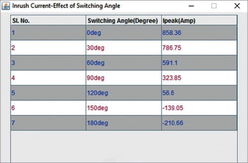
It can be seen from these results that as the switching angle increases, the value of Ipeak decreases.
Harmonic Analysis
Results are displayed in tabular form as shown in Fig. 8.
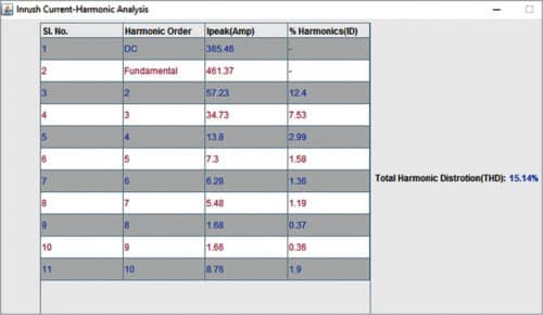
Total Harmonic Distortion (THD): 15.14%
It is obvious from above results that the second harmonic is the most dominating harmonic component in inrush current and accounts for almost 80 per cent of THD.
Effect of various transformer parameters on inrush current
This software can give a useful insight into the effect of various transformer parameters on inrush current. Some of these effects are described below.
Effects of system resistance
The effects of system resistance can be considered by varying the value of resistance while keeping other parameters constant. It can be seen that increasing the resistance causes faster decay in the amplitude of inrush current. Therefore it can be said that transformers located closer to the generating plants have a small value of system resistance and thus display higher amount of inrush currents lasting much longer than the transformer installed electrically away from the generator (as they have higher system resistance).
This effect can be analysed in the above testing example by varying the value of source resistance while keeping all other parameters constant. The results are shown in Table I.
Analysis of results. Current does not decay when resistance is zero. This clearly shows that inrush current decays because of damping produced by system resistance.
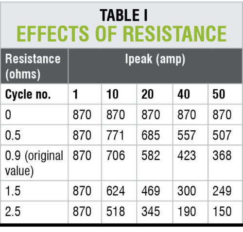
As the overall resistance increases due to increase in system resistance (transformer winding resistance is constant), inrush current decays faster. This can be observed by comparing the value of inrush current at different cycles for various values of resistance.
Effects of the core material
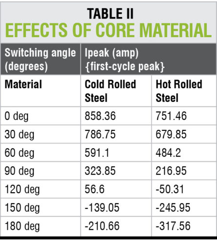
The effect of core material and thus the effect of residual flux density (Br) can be analysed in the above example by selecting different core materials while keeping all other parameters constant. The results are shown in Table II.
Analysis of results
As is seen from Table II, the first-cycle peak current changes significantly when the residual flux varies (with change in core material). Also the results indicate that switching at =90° may not necessarily reduce the magnitude of inrush current. So, for reducing inrush current, an appropriate switching angle by considering residual flux must be selected.
Applications
This software can be very useful for design engineers, practising engineers and electrical engineering students to study and analyse the behaviour of inrush current under different operating conditions and for different transformer parameters. For example, design engineers can select appropriate values of peak flux density, core material, saturation flux density and transformer dimensions to estimate the value of inrush current, effect of switching angle and harmonic effects before transformer manufacturing and thus can optimise the transformer design.
Download Source Code: click here
This article was first published on 28 February 2018 and was updated on 21 March 2020.


