Today, almost all applications are expected to be wireless, consume very little power and have high data retention capability.
For this, selection of an effective media at the physical layer is important. Today, several wireless devices featuring ZigBee protocol, IR transceiver, RF transceiver and dish antennas are commonly used. Antenna plays a vital role in all these devices.
A good antenna design can result in a high degree of efficiency, better directivity and more beamwidth for long-distance transmission without much loss of information. Here is a program written in MATLAB for designing antenna arrays & antenna analysis.
Before delving into the MATLAB program, let’s go through the basics of some parameters required for antenna analysis & design, such as signal radiation pattern, sidelobes, efficiency, beamwidth and directivity.
Antenna basics
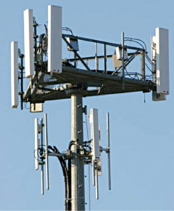
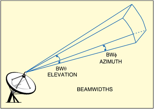
Fig. 1 shows the aperture of a typical antenna. Here BWΦ denotes the azimuth beamwidth and BWθ the elevation beamwidth. Beamwidth is normally measured at the half-power or -3dB point of the main lobe, unless otherwise specified.
According to the official website of the Antartic Impulsive Transient Antenna (ANITA, www.phys.hawaii.edu/~anita/new/papers/militaryHandbook/antennas.pdf), the gain or directivity of the antenna is the ratio of the radiation intensity in a given direction to the radiation intensity averaged over all directions. The difference between directivity and gain is that the directivity neglects antenna losses such as dielectric, resistance, polarisation and voltage standing wave ratio (VSWR) losses. Since these losses are usually quite small in most classes of antennas, directivity and gain are approximately equal, disregarding unwanted pattern characteristics.
However, antennas are different practically, and do not have ideal radiation distribution. Energy varies with angular displacement and losses occur due to sidelobes.
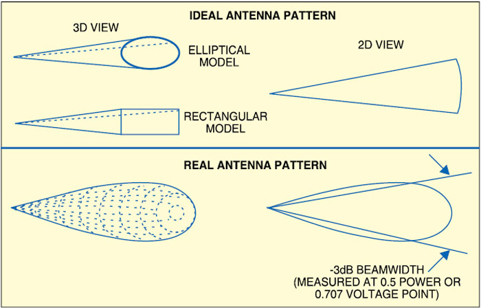
If you can measure the radiation pattern, and determine the beamwidth, you can use two or more ideal antenna models to approximate a real antenna pattern as shown in Fig. 2. Assuming the antenna pattern to be uniform, gain G is equal to the area of the isotropic sphere divided by the sector (cross-section) area as:

Antenna efficiency is a factor that includes all reductions from the maximum gain. It can be expressed as a percentage or in dB. Several types of losses must be accounted for while determining the efficiency:
1. Illumination efficiency, which is the ratio of the directivity of the antenna to that of a uniformly illuminated antenna of the same aperture size
2. Phase-error loss or loss due to the aperture not being a uniform phase surface
3. Spillover loss (for reflector antennas), which reflects the energy spilling beyond the edge of the reflector into the back lobes of the antenna
4. Mismatch loss expressed as voltage standing wave ratio (VSWR), derived from the reflection at the feed port due to impedance mismatch—especially important for low-frequency antennas
5. RF losses between the antenna and the antenna feed port or measurement point
Effective capture area (Ae) is the product of the physical aperture area (A) and the aperture efficiency (η):

Thus gain is a function of aperture efficiency.
The gain of an antenna with losses is given by:
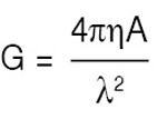
where ‘η’ is aperture efficiency, ‘A’ physical aperture area and ‘λ’ wavelength.
Note that the gain is proportional to the aperture area and inversely proportional to the square of the wavelength. So if the frequency is doubled, or the wavelength halved, the aperture could be decreased four times to maintain the same gain.
Radiation patterns of various antennas
According to ANITA’s website, radiation patterns of the antennas presented in the previous section are for the most commonly used antenna geometries. The antenna should be viewed as a matching network that takes the power from a transmission line (50-ohm, for example) and matches it to the free space impedance of 377 ohms. The most critical parameter is the change of VSWR with frequency. The pattern usually does not vary much from acceptable to the start of unacceptable VSWRs (>2:1). For a given physical antenna geometric size, the actual radiation pattern varies with frequency.
Antenna arrays
According to AntennaTheory.com, an antenna array, often called a ‘phased array,’ is a set of two or more antennas, as shown in Fig. 3. The signals from the antennas are combined or processed in order to achieve improved performance over a single antenna.
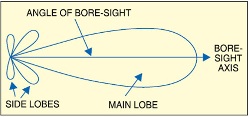
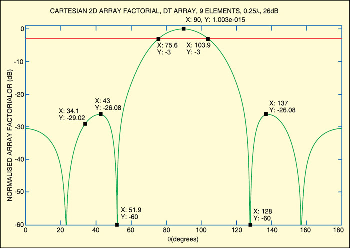
It is generally noticed that the antenna array factors for arrays with uniform weights have unequal sidelobe levels (refer Fig. 4). Often, it is desirable to reduce the highest sidelobes at the expense of increasing number of lower sidelobes. The optimal sidelobe level for a specified beamwidth will occur when the sidelobes are all equal in magnitude.
There is a method for obtaining weights for uniformly spaced linear arrays steered to broadside (θd=90 degrees). It is a popular weighting method because the sidelobe level can be specified, and the minimum possible null-null beamwidth obtained.
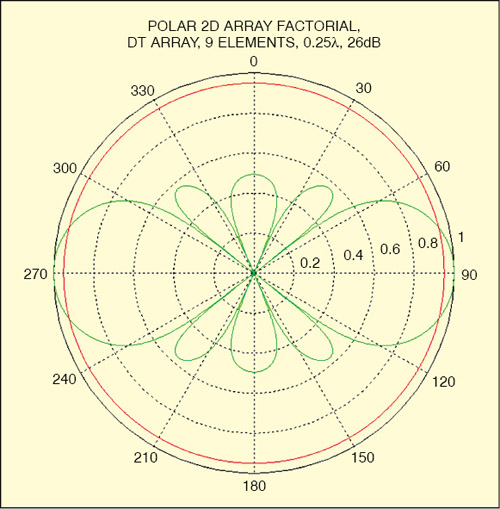
Figs 5 and 6 show cartesian and polar plots of the antenna radiation pattern, respectively. Effective selection of lamda (λ) and the number of elements can reduce the sidelobe level of antenna.
Yagi-Uda antenna
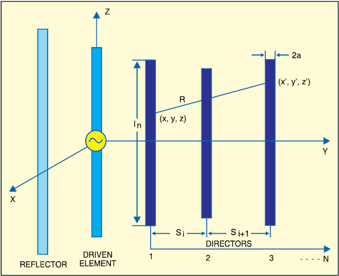
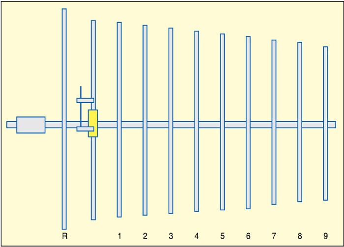
Yagi-Uda antenna (refer Fig. 7) is the most common terrestrial TV antenna used on the rooftops. It is usually used at frequencies between 30 MHz and 3 GHz, or a wavelength range of 10 metres to 10 cm.
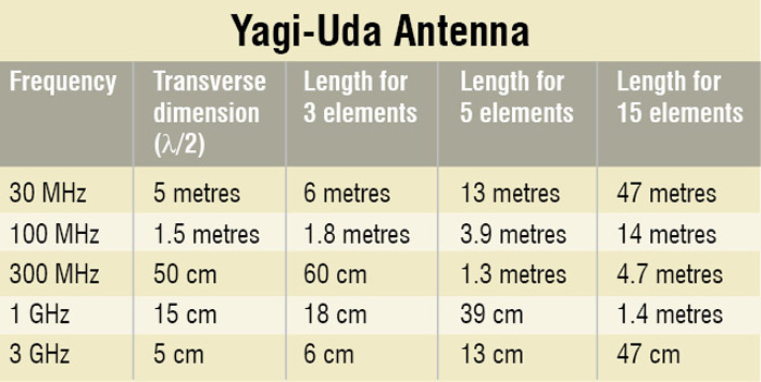
The design of the antenna depends on the number of elements used in the antenna. The lengths of rods in a Yagi-Uda are about a half wavelength each, and the spacing of the elements about one-third of a wavelength.
As shown in the table, you can estimate the approximate operating frequency of a Yagi-Uda antenna by looking at its length from afar. A Yagi-Uda antenna with eleven elements is shown in Fig. 8.
To obtain the radiation pattern of a Yagi-Uda antenna in MATLAB program, a table with theta (or θ) values for polar angles and corresponding amplitudes of radiation patterns is required. These values can be obtained using antenna trainer. The data table should be saved in text (.txt) format.
MATLAB program
MATLAB R2008b or higher versions can be used for the program. The step-by-step procedure for program testing follows:
1. Run MATLAB from Desktop
2. Open ‘Expt_A1_2D.m’ file from ‘File’ menu
3. Import ‘Polalist-yagi uda.txt’ file from ‘File’ menu by selecting “Import Data” option
4. Click ‘Next’ button
5. Click ‘Finish’ button
6. Compile and run the program from ‘Debug’ menu by clicking ‘Run’ option
7. Go to the main MATLAB window. The command window will prompt you to enter the offset value for theta
8. Enter value like 90, 80 or anything as per your requirement and then press ‘Enter’ key
9. You should get the directivity output plots in polar as well as in cartesian forms
On entering the appropriate value, the program gives a good directivity plot. Maximum directivity is 4.483 or 6.5157 dB.
Download source code: click here


open all source
I clicked on the source code but could not download
Kindly refresh the page and redownload the Source Code.
I got an error in program line 5??? And what is data ???? Plzzz help me
What is the error message you got?
im not able to download the file could u pls help me?
Dear Teja, Kindly check your internet connection. From our side we are able to download the source file.
this project is based on which type of antenna? could u please provide me more details about this
Have you download it till now or not
error in matlab2016a:
Undefined function or variable ‘data’.
Error in Expt_A1_2D_Antenna_Polar_Radiation_Pattern (line 8)
if ((size(data)~= [360,2])&&(size(data)~= [72,2]));
Undefined function or variable ‘data’.
Error in Expt_A2_2D_Antenna_Directivity (line 6)
if ((size(data)~= [360,2])&(size(data)~= [72,2]));
i too got the same error what should i do?
What is data .? ?
Kindly elaborate your query.
matlab code is based on which type of antenna can i get detail explanation of program
Please go through the text again to get more detail on the type of antenna. It is for antenna array type including Yagi-Uda type…
Sir,Is it necessary to add any SUPPORTS TO MATLAB for proper execution of this project
sir,
could you please help me in getting the matlab code for parameters of 9 element yagi uda antenna.
i cannot find the matlab code where is it
The source code is present on the second page.
sir, i got error like this
Undefined function or variable ‘data’.
Error in a22 (line 5)
if ((size(data)~= [360,2])&(size(data)~=
[72,2]));
what should i do now?
I successfully ran the program
where is the download link?
The source code is present at the end of the article.
I can’t download source code.
Hi, Kindly temporarily turn off the antivirus and then download the zip file.
Please send the array antenna
Kindly elaborate your query.