


While designing electronic circuits, component values are calculated using formulae from the circuit’s theory. These calculations waste a lot of time. This circuit design calculator software developed in MATLAB, JavaScript, etc help you solve, analyse and determine the circuit design with capacitors, inductors, resistors, diodes, transistors and other components. The software can provide answers to many complex analogue and digital circuit design problems. Here we present four programs developed in ‘C++’ language to calculate values of the components used in tank and voltage regulator circuits.
Circuit design parameters
Before writing the program, it is necessary to study the zener voltage regulator and tank circuits:
Zener voltage regulator
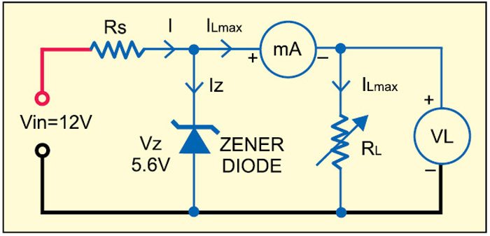
The zener voltage regulator circuit consists of series resistor Rs, zener diode and load resistor RL as shown in Fig. 1. It is used to stabilise the DC voltage of the circuit even if the input voltage varies in certain range. It is also used to eliminate AC components present in the DC voltage. Normally, it is required to calculate the value of series resistor Rs, its wattage and zener wattage according to the load current of the different circuits.

Let’s say, minimum zener current Iz is 5 mA. Total current I=Iz+ILmax
The value of series resistor Rs is given by:
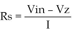
where Vin is the input DC voltage in volts, Vz zener voltage in volts and ‘I’ total current in amperes. For testing we have used Vz=5.6V and Vin=12V, but other values can also be used.
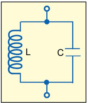
Tank circuit
This circuit is a parallel combination of an inductor and a capacitor (see Fig. 2). It is used in RF oscillators, which are also used in AM and FM modulators in broadcast stations or TV relay stations.
The frequency of the tank circuit is given by:
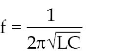
where ‘f’ is the frequency in hertz, ‘L’ inductance in henry and ‘C’ capacitance in Farads.
Software operation
This project includes programs to calculate various parameters including zener regulation, and frequency, inductance as well as capacitance of the tank circuit. The user has to select one of these program options. Formulae for a particular electronic circuit are included in the code. When a program is run, it prompts the user to enter the required data. After the data is entered, the result is displayed in a fraction of a second.
Zener regulation
When zener regulation program is selected, it prompts you to enter the input voltage, zener voltage and total current through resistor Rs. After the values are entered, the program executes to calculate the values of series resistor Rs and power dissipated across the series resistor, and displays the power across the zener diode immediately.
Frequency of tank circuit
When this program is selected, you have to enter the values of inductance and capacitance. The program displays the frequency of tank circuit.
Inductance of tank circuit
When this program is selected, enter the values of frequency and capacitance. The inductance of tank circuit is displayed immediately.
Capacitance of tank circuit
When this option is selected, enter the values of frequency and inductance. The program will display the capacitance of the tank circuit.
Download source code: click here

The link is dead? I know it’s an old article but does someone have the code, I would like to examine it?
Thank you Edo, the link is updated now.
I m not able to download the source code.Can u please update it
Please refresh the page to download the source code.
The codes are in cpp format.can you help me to convert them to matlab codes?
no