


In priority encoder, if two or more inputs are equal to 1 at the same time, the input having the highest priority will take precedence. In case of dual-priority encoder, the circuit identifies both the highest-priority and the second-highest-priority asserted signal among a set of input signals. Presented here is an eight-input dual-priority encoder designed using LabView versions 12. In LabView, Front Panel serves as the user interface and Block Diagram contains the graphical source code that defines the functionality of the virtual instrument (VI). Following are the steps required to design dual-priority encoder using NI’s LabView:
Step 1. Open LabView and press Ctrl+N followed by Ctrl+T keys to open the tiling Front Panel and Block Diagram.
Step 2. Go to Front Panel and from the menu bar select View->Controls ->Modern->Push Button (this is where we give input), drag and drop it on to Front Panel and label it as input I0. Similarly, select seven such inputs and label them as I1, I2, I3, I4, I5, I6 and I7. Arrange them in sequential order as shown in Fig. 1. Here, input I7 has the highest priority.
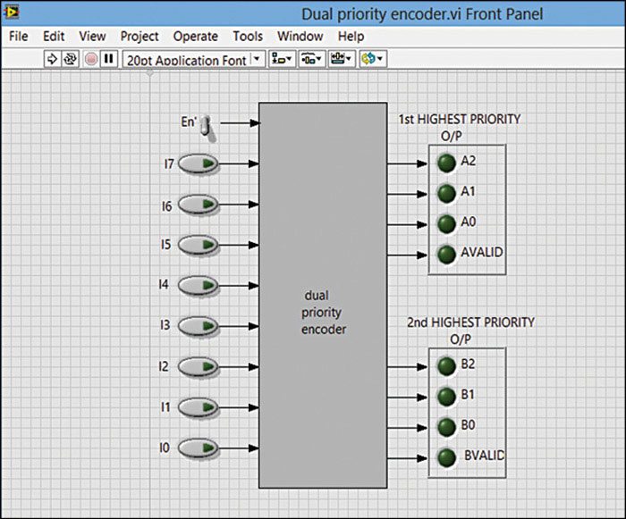
Step 3. Select View->Controls-> Modern->Boolean-> Vertical Toggle switch and label it as En’, place it above the inputs. This is an active low enable input.
Step 4. Select Modern-> Decorations-> Flat Frame and adjust its size such that all the inputs are positioned on its left side for neat appearance. Double left click on the Front Panel and type ‘dual priority encoder’ and drag it inside the frame.
Step 5. Select Modern-> Boolean-> Round LED (this is where we see the output) and drop it on to Front Panel and label it as output A2. Similarly, select other three such outputs and label them as A1, A0 and AVALID. These will be used for the first-highest-priority encoder output. Following the same steps as above, label them as B2, B1, B0 and BVALID for the second-highest-priority encoder output. Arrange them in sequential order as shown in Fig. 1.
Step 6. Select Modern -> Decorations -> Recessed Frame and adjust its size such that the outputs (A2, A1, A0 and AVALID) are positioned inside the frame for neat appearance. Similarly, arrange the remaining outputs (B2, B1, B0 and BVALID) in another recessed frame.
Step 7. Use A[2:0] and AVALID to identify the highest-priority request, where AVALID is asserted only if at least one request input is asserted. Use B[2:0] and BVALID to identify the second-highest-priority request, where BVALID is asserted only if at least two request inputs are asserted.
Right click on the Front Panel, select Modern->Decoration->Thin Line with Arrow option and drag and drop on the Front Panel and place the arrow to each input line as shown in Fig. 1.
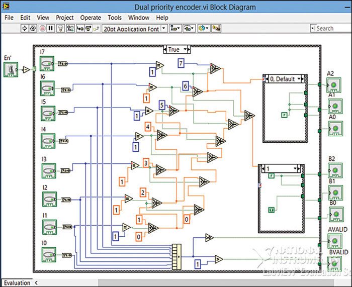
Step 8. Go to Block Diagram workspace (refer Fig. 2) and select View-> Functions -> Programming-> Structures-> Case Structure and drop it on to Block Diagram. (Note. Three Case Structures are used in this project; this will be considered as main Case Structure.) The labels in the menu at the top of the Case Structure will appear as True and False. First consider the True condition.
Step 9. Select Programming-> Boolean-> NOT gate and drop it on to Block Diagram. Place the cursor at output of vertical toggle switch (En’). You will see a hot spot. From there pull a wire and give it as input to NOT gate. The output of NOT gate is connected to the selector terminal ‘?’ of the Case Structure.
Step 10. Again, select Programming-> Boolean-> Bool to (0, 1) function and drop it on to Block Diagram. Connect the output of I7 to input of Bool to (0, 1) function.
Step 11. Select Programming-> Comparison-> Equal ? function and drop it on to Block Diagram. Give the output of ‘Bool to (0, 1)’ to one of the inputs of ‘Equal ?’. Place cursor on the second input of ‘Equal ?’ and right click on it. Select Create->Constant and put value 1.
Step 12. Select Programming-> Comparison-> Select function and drop it on to Block Diagram. It has three input lines, namely, true (t), select (s) and false (f). Connect the output of ‘Equal ?’ to ‘s’ input of Select function.
Step 13. Repeat steps 10, 11 and 12 for remaining inputs (I6, I5…I1), except for I0.
Step 14. Place cursor on the true (t) input of Select function, right click on it and create a constant of value 7 for input I7. Similarly, do it for all inputs with constant value decreased by 1 for each input of Select function, which are arranged in descending order as shown in Fig. 2.