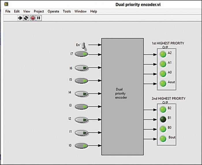
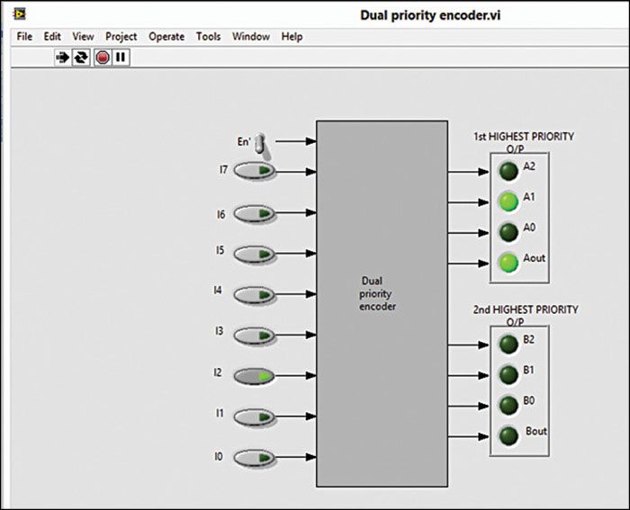
Step 15. Connect the output of Select function corresponding to I1 to false (f) input of Select function corresponding to I2. Similarly, connect the remaining outputs of Select function to false (f) input of the Select function, except for I7. Create a constant 0 for the false (f) input of Select function of input I1.
Step 16. Add two Case Structures as explained below. Select Programming-> Structures-> Case Structure, drag and drop it on to Block Diagram inside the main Case Structure. If labels in the menu appear as True and False, modify them to 0 and 1, respectively. Right click on case selector or menu, select ‘Add Case After’ option and label it as 2. Similarly, do the same for the other five cases and label them as 3, 4, 5, 6 and 7.
Step 17. Connect the output of the Select function of I7 to selector terminal ‘?’ of the inner upper Case Structure.
Step 18. Select case 0 and then select Programming->Boolean-> False Constant and connect the output of False Constant (labeled as F) to the Round LED A2, which is placed outside the Case Structures. An open box called Tunnel will be created on both main and upper Case Structure boundaries.
Step 19. Place the curser on the output wire of F. You will find a hot spot. Click on it and draw two more wires to connect to A1 and A0, respectively. Thus we have connected F to A2, A1 and A0 to represent the binary number for the case 0. That is, the binary number for decimal number zero for [A2 A1 A0] is [0 0 0]. Now, if case 1 is selected, the binary representation of outputs A2 A1 A0 will be 0 0 1. Here, F should be connected to A2 and A1 for the 0s. For 1 we will consider the True (T) Constant by selecting Programming->Boolean-> True Constant option. That is, connect T to A0. For case 2, the binary output of [A2 A1 A0] is [0 1 0] and for case 3 the output is [0 1 1], and so on.
Step 20. Similarly, connect False (F) and True (T) constants to outputs (A2, A1, A0) for remaining cases to represent the corresponding binary number. We can follow the same technique for the inner lower Case Structure.
Step 21. Select another Select function and place in the main Case Structure. Connect output of ‘Equal ?’ correspond to input I7 to the ‘s’ input of Select function. These are used to select the second-highest-priority request. Similarly, do it for the remaining inputs, except for I0.
Step 22. Connect ‘t’ inputs of Select functions from the output of previous Select functions as shown in Fig. 2, except first Select function of I7.
Step 23. Connect output of Select function corresponding to I1 to the ‘f’ input of the Select function corresponding to I2. Similarly, repeat the same connection at the Select functions corresponding to I3 through I6 inputs, except for I7. And then create a constant 0 at ‘f’ input of Select function corresponding to input I0.


Step 24. Select another Case Structure and drop it on to Block Diagram inside the main Case Structure. If labels appear as True and False, modify them to 0 and 1, respectively and then add six more cases and label them as 2, 3, 4, 5, 6 and 7.
Step 25. Connect the output of the second Select function of I7 to selector terminal ‘?’ of the inner lower Case Structure. And then repeat steps 18 and 19 for outputs B2, B1 and B0.
Step 26. Select Programming-> Numeric-> Compound Arithmetic and drop it on to Block Diagram. Extend it so that it has eight inputs. Now, connect the eight outputs from Boolean (0, 1) functions to the eight inputs of Compound Arithmetic. Change the mode of Compound Arithmetic to ‘Add’ by right clicking on it and select Change Mode-> Add option. This will add a ‘+’ sign to it to make it an adder function.
Step 27. Select Programming-> Comparison->Greater ? and drop it on to Block Diagram inside the main Case Structure. Give the output of Compound Arithmetic adder to the first input ‘x’ of Greater ?. Place cursor on the second input ‘y’ and right clicking on it create a constant of value 1.
Step 28. Connect the output of Greater ? to Round LED BVALID and draw another wire from output of Compound Arithmetic adder to input of another comparison function ‘Greater Than 0?’ Give the output of it to another Round LED AVALID.


